
Patsnap Eureka
For R&D, Patsnap Eureka makes reading and utilizing patents & technical documents easy.
Patsnap Eureka AIR
Designed for self-driven R&D workflows. Generate viable solutions, solve complex R&D challenges, empower your innovation with AI.

Patsnap Eureka Materials
Designed for material experts only. Revolutionize your material R&D, from search, analyze, to developing new materials.

TechResearch
Generate reliable direction feasibility study reports for your R&D in just a few steps.

TechSeek
Discover and master advanced knowledge NOW. Basics, ideas, possibilities, all at once.

TechMind
As an expert in R&D Theories, TechMind can generates customized viable solutions instantly.

TechRisk
Analyze your overall solution with one click, know your potential R&D risks in advance.

TechMonitor
Get weekly tech updates, stay abreast of the latest tech innovations and key insights.
Hollow glass spacing strip cutting machine
A strip cutting machine, glass technology, applied in the direction of metal sawing equipment, sawing machine, metal processing equipment, etc., can solve the problems of unsafe cutting and operation, and achieve the effect of reducing cutting errors, good stability, and convenient cleaning
- Summary
- Abstract
- Description
- Claims
- Application Information
AI Technical Summary
Problems solved by technology
Method used
Image

Examples
Embodiment
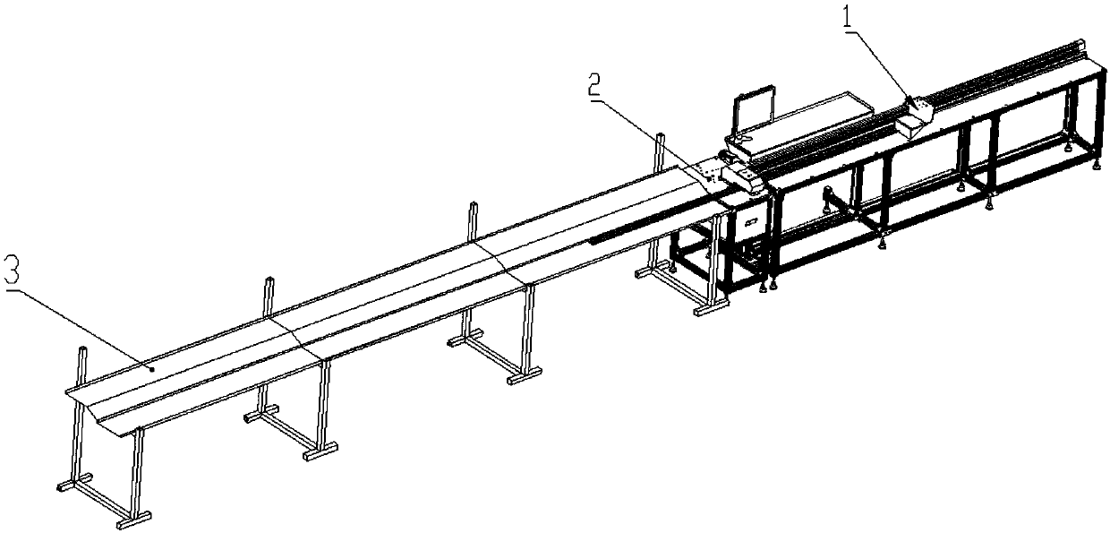
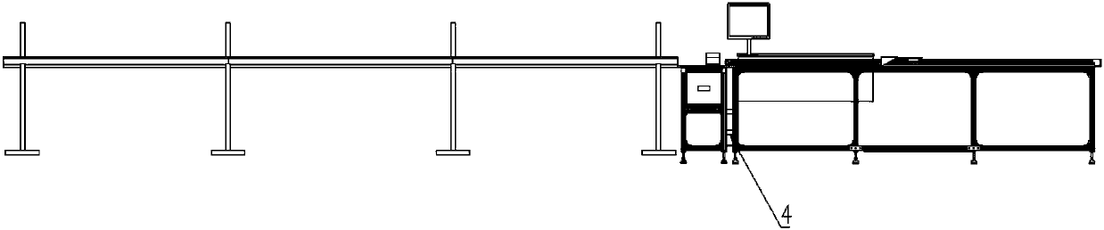
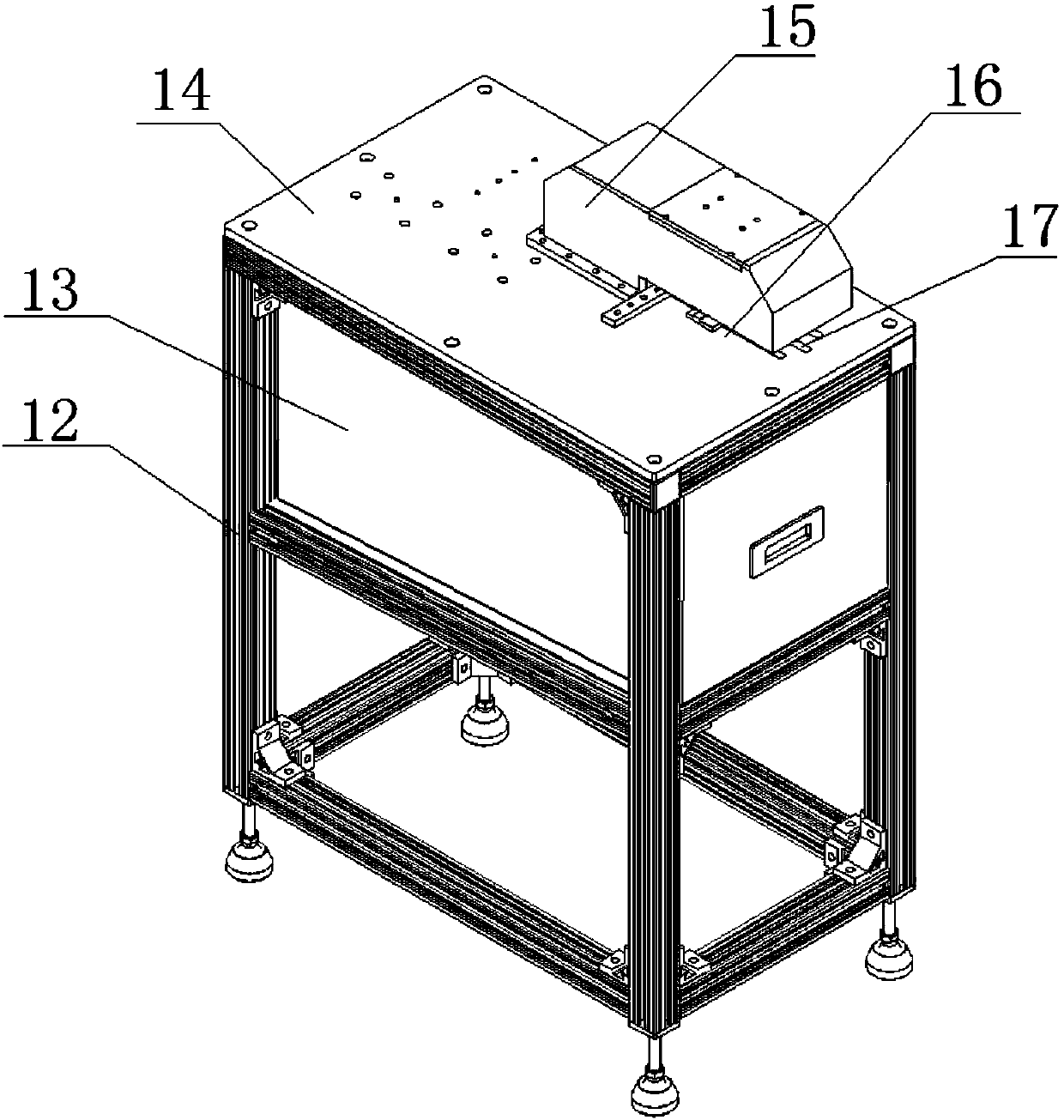
[0038] Such as Figure 1-Figure 10 As shown, a hollow glass spacer cutting machine includes a cutting platform 2 and a material receiving platform 3 and a positioning platform 1 respectively located on both sides of the cutting platform 2; the cutting platform 2 includes a bracket 12, and the upper end of the bracket 12 is provided with a mounting plate 14. The upper end surface of the mounting plate 14 is provided with a saw blade guard 15, and a feed channel 16 is left between the saw blade guard 15 and the mounting plate 14, and the mounting plate 14 is located at the position of the feed channel 16 and is provided with an opening groove 17; The lower end surface of the mounting plate 14 is also provided with a slide table cylinder 18, the piston rod of the slide table cylinder 18 is connected with a cutting motor 23, and the output shaft of the cutting motor 23 is connected with a saw blade 22, and the saw blade 22 is partially stretched out of the opening. Groove 17; arou...
Embodiment 1
[0056] Based on Embodiment 1, a three-axis cylinder 19 is arranged vertically inside the saw blade guard 15 of this embodiment. The piston rod of the three-axis cylinder 19 is connected to a pressure plate 20 , and a saw blade relief groove 24 is provided on the pressure plate 20 . One end of the piston rod of the three-axis cylinder 19 has a certain degree of floating, and the pressure plate 20 moves up and down under the action of the three-axis cylinder 19 to compress or loosen the spacer, and has a certain floating and rotating effect during the compression process. Assembly requirements Low, good protection for the spacer, and the saw blade relief groove 24 is set at the same time for the movement of the saw blade 22 to ensure the normal cutting of the saw blade 22.
[0057] Based on the above technical solution, the lower end of the pressure plate 20 is located on both sides of the saw blade relief groove 24 and is connected with polyurethane pressing blocks 21 . Due to ...
Embodiment 1 or Embodiment 2
[0059] Based on Embodiment 1 or Embodiment 2, the following structure is further added in this embodiment: the cutting machine also includes a spacer bar clamping device arranged on the upper end surface of the mounting plate 14, and the spacer bar clamping device includes fixed positioning baffles arranged at intervals 27 and movable positioning baffle plate 25, described mounting plate 14 lower end surfaces are also provided with miniature cylinder 26, the piston rod of miniature cylinder 26 is connected with pin shaft by joint bearing, and pin shaft passes through mounting plate 14 and connects with described movable positioning baffle plate 25 connections.
[0060] In this embodiment, the fixed positioning baffle plate 27 and the movable positioning baffle plate 25 can be combined to carry out horizontal positioning and clamping of the spacer bar. The side can be positioned and clamped by the movable positioning baffle 25, and finally the upper end surface is pressed by th...
PUM
 Abstract
Description
Claims
Application Information
 - R&D Engineer
- R&D Manager
- IP Professional
- Industry Leading Data Capabilities
- Powerful AI technology
- Patent DNA Extraction
Browse by: Latest US Patents, China's latest patents, Technical Efficacy Thesaurus, Application Domain, Technology Topic, Popular Technical Reports.
© 2024 PatSnap. All rights reserved.Legal|Privacy policy|Modern Slavery Act Transparency Statement|Sitemap|About US| Contact US: help@patsnap.com