


Quick Research
Generate reliable direction feasibility study reports for your R&D in just a few steps.

Technical Q&A
Discover and master advanced knowledge NOW. Basics, ideas, possibilities, all at once.

Find Solutions
As an expert in R&D theories, this can generate solutions to your technical problems instantly.

Evaluate Feasibility
Analyze your overall solution with one click, know your potential R&D risks in advance.

Monitor Landscape
Get weekly tech updates, stay abreast of the latest tech innovations and key insights.
All-dielectric reflection-type efficient ultra-thin beam splitter and preparation method and application thereof
A reflective, all-dielectric technology, used in instruments, optics, optical components, etc., can solve problems such as low average reflectivity, and achieve the effects of high reflection efficiency, low time cost, and wide source of raw materials
- Summary
- Abstract
- Description
- Claims
- Application Information
AI Technical Summary
Problems solved by technology
Method used
Image


Examples
preparation example Construction
[0065] Another aspect of the embodiments of the present invention provides a method for preparing the above-mentioned all-dielectric reflection type high-efficiency ultra-thin beam splitter, which includes: alternately stacking high-refractive index dielectric materials and low-refractive index dielectric materials on the substrate to form high-efficiency stacks reflector;
[0066] setting a dielectric transmission layer on the high-efficiency stacked reflector;
[0067]A dielectric functional layer is arranged on the dielectric transmission layer, and a periodic nano-column array structure is formed in the dielectric functional layer.
[0068] Further, the preparation method includes: forming the high-efficiency laminated reflector on the substrate by magnetron sputtering coating technology.
[0069] Further, the preparation method includes: forming the dielectric transmission layer on the high-efficiency stacked reflector by using magnetron sputtering coating technology.
...
Embodiment 1
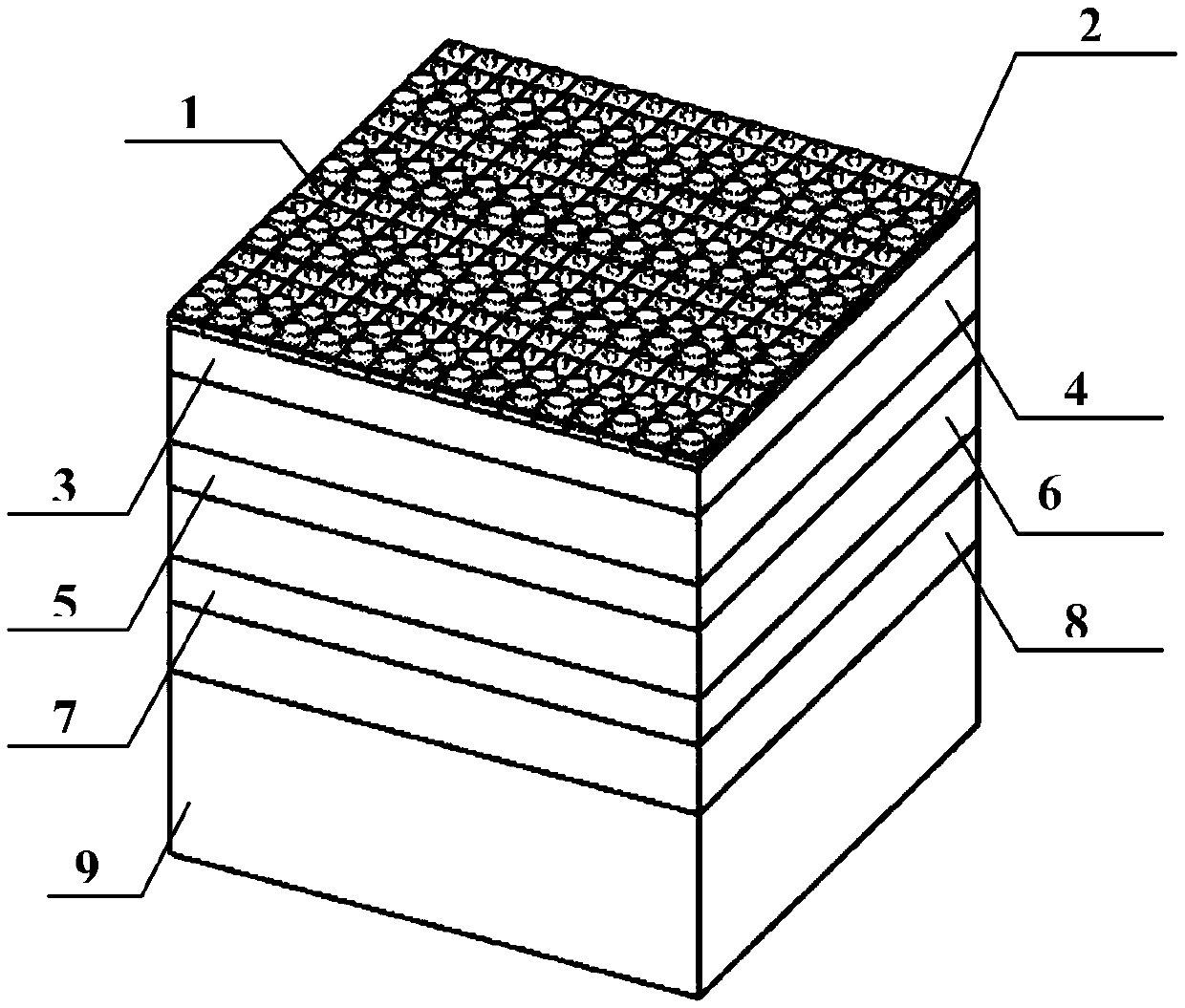
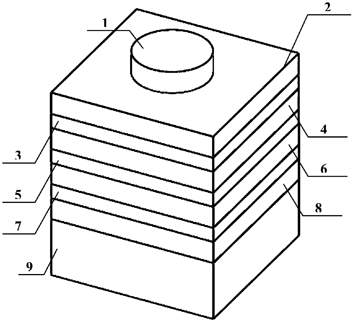
[0079] see figure 1 As shown, an all-dielectric reflection type high-efficiency ultra-thin beam splitter in this embodiment includes a silicon nano-pillar array structure 1 formed by alternating arrangement of silicon nano-pillars 10 with designed diameters in an "AABB" manner, and a magnesium fluoride dielectric transmission Layer 2, the high-refractive-index silicon dielectric layers 3, 5, and 7 that constitute the high-efficiency stacked reflector with a DBR-like structure, and the low-refractive-index magnesium fluoride dielectric layers 4, 6, and 8 that constitute the high-efficiency stacked reflector with a DBR-like structure, silicon Substrate9. A beam of visible light (450nm-760nm) is vertically incident on the all-dielectric reflection type high-efficiency ultra-thin beam splitter from the top of the device, and is efficiently reflected into two beams of the same visible light. The frequency and polarization direction of the light do not change, that is It is an all-...
PUM
 Abstract
Description
Claims
Application Information
 - R&D Engineer
- R&D Manager
- IP Professional
- Industry Leading Data Capabilities
- Powerful AI technology
- Patent DNA Extraction
Browse by: Latest US Patents, China's latest patents, Technical Efficacy Thesaurus, Application Domain, Technology Topic, Popular Technical Reports.
© 2024 PatSnap. All rights reserved.Legal|Privacy policy|Modern Slavery Act Transparency Statement|Sitemap|About US| Contact US: help@patsnap.com