Catalyst-adhered body production method and catalyst adhesion device
A catalyst carrier and catalyst technology, which can be used in catalyst activation/preparation, chemical instruments and methods, physical/chemical process catalysts, etc., can solve problems such as the inability to fully reduce manufacturing costs, and achieve the effect of good manufacturing efficiency.
- Summary
- Abstract
- Description
- Claims
- Application Information
AI Technical Summary
Problems solved by technology
Method used
Image

Examples
Embodiment 1
[0134]
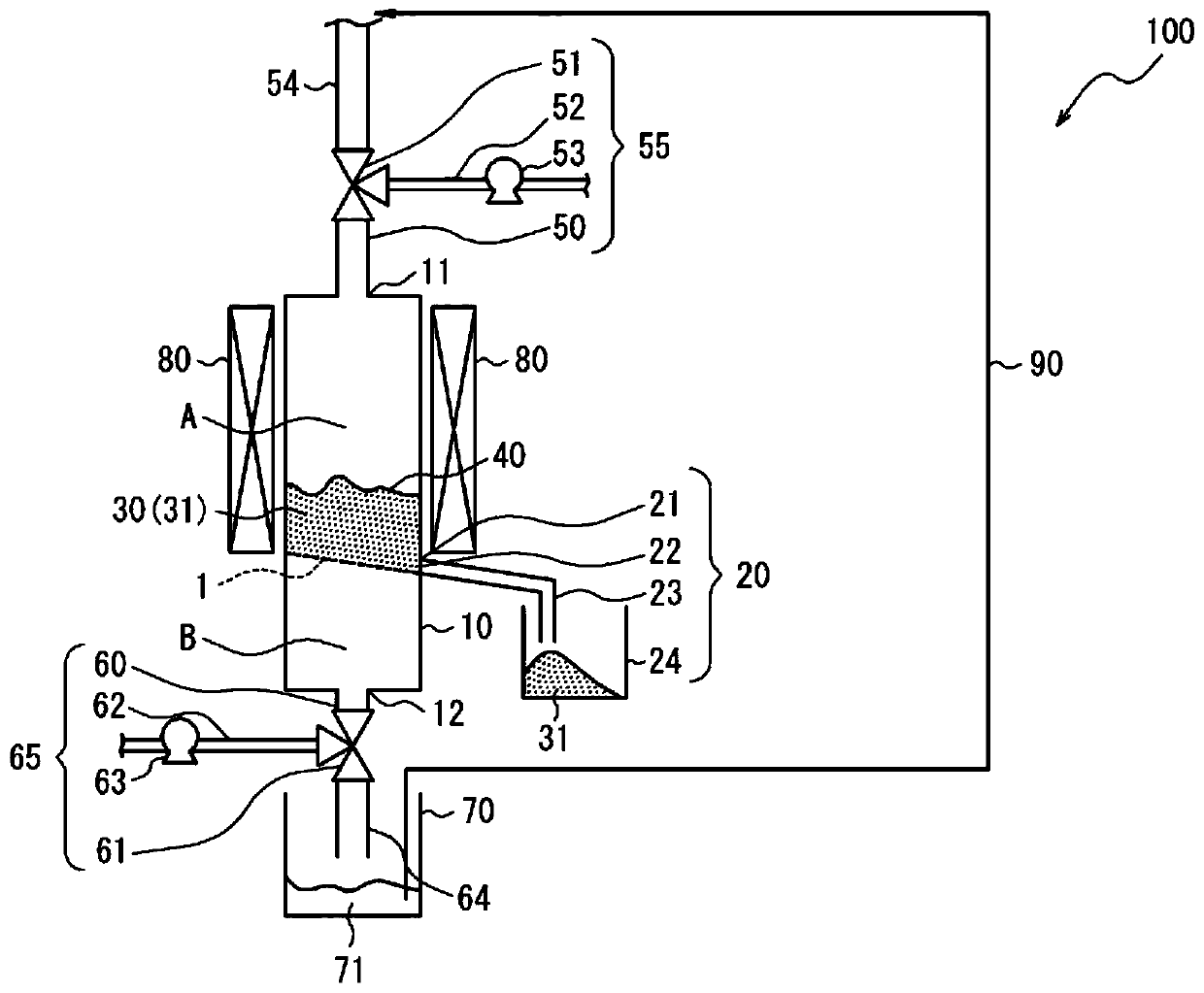
[0135] A catalyst-attached body manufacturing apparatus having a container composed of a quartz tube with an inner diameter of 2.2 cm and having a porous plate (sintered body with a mesh of 0.1 mm) in the lower portion was used. The container was filled with 30 g of alumina beads (volume average particle diameter D50: 0.3 mm) as target particles. Then, 30 mM iron acetate (Fe(CH 3 COO) 2 )·36mM aluminum isopropoxide (Al(OC 3 h 7 ) 3 )·Ethanol solution (the first attachment process). At this time, all the alumina beads in the quartz tube were immersed in the catalyst-catalyst carrier raw material mixed solution.
[0136] Then, nitrogen gas was flowed from the upper pipe connected to the upper part of the quartz tube to remove the residual liquid of the catalyst-catalyst carrier material mixed solution from the quartz tube (the first residual liquid removal process), and the particles in the quartz tube were dried as the adhered particles. alumina beads (the firs...
Embodiment 2
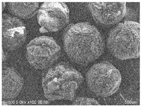
[0142] In addition to changing the catalyst-catalyst support material mixed solution used in the first attachment process and the second attachment process to 30 mM iron acetate (Fe(CH 3 COO) 2 )·24mM aluminum isopropoxide (Al(OC 3 h 7 ) 3 ) and ethanol solution, in the same manner as in Example 1, the production of the catalyst-attached body and the synthesis of CNTs were carried out. Table 1 shows the results. in addition, image 3 An image of the synthesized catalyst carrier is shown.
Embodiment 3
[0144] After carrying out the attachment step using the catalyst carrier raw material solution to the drying step, the raw material decomposition step to the post-decomposition drying step were carried out. After repeating this series of steps for 3 sets, a set of catalyst-catalyst carrier raw material was implemented. Adhesion process of mixed solution to drying process.
[0145] In the attachment step to the drying step using the catalyst carrier raw material solution, instead of the catalyst-catalyst carrier raw material mixed solution, 48 mM aluminum isopropoxide (Al(OC 3 h 7 ) 3 ) ethanol solution as the catalyst carrier raw material solution, and in the raw material decomposition process, use ion-exchanged water to replace the 0.1M ammonia solution, and do not use a heating device in the drying process and the drying process after decomposition. In addition to the above points, implement the same The same operations as the first attachment step to the first drying step...
PUM
| Property | Measurement | Unit |
|---|---|---|
| particle size | aaaaa | aaaaa |
| particle size | aaaaa | aaaaa |
| particle size | aaaaa | aaaaa |
Abstract
Description
Claims
Application Information
 - R&D
- Intellectual Property
- Life Sciences
- Materials
- Tech Scout
- Unparalleled Data Quality
- Higher Quality Content
- 60% Fewer Hallucinations
Browse by: Latest US Patents, China's latest patents, Technical Efficacy Thesaurus, Application Domain, Technology Topic, Popular Technical Reports.
© 2025 PatSnap. All rights reserved.Legal|Privacy policy|Modern Slavery Act Transparency Statement|Sitemap|About US| Contact US: help@patsnap.com