Low-pass filter circuit, low-pass filter, and CMOS chip

A low-pass filter circuit and resistor technology, which is applied in the direction of electrical components, impedance networks, multi-terminal pair networks, etc., can solve problems such as unfavorable realization of low-pass filters

Pending Publication Date: 2019-10-08
HUNAN GOKE MICROELECTRONICS
View PDF10 Cites 3 Cited by
  • Summary
  • Abstract
  • Description
  • Claims
  • Application Information

AI Technical Summary

Problems solved by technology

[0004] Based on this, it is necessary to provide a low-pass filter circuit, a low-pass filter and a CMOS chip that can be implemented in an integrated circuit for the problem that the above-mentioned low-pass filter is not conducive to implementation in an integrated circuit.

Method used


Image

  • Low-pass filter circuit, low-pass filter, and CMOS chip
  • Low-pass filter circuit, low-pass filter, and CMOS chip
  • Low-pass filter circuit, low-pass filter, and CMOS chip

Examples


Embodiment Construction

[0020] In order to facilitate the understanding of the present application, the present application will be described more fully below with reference to the relevant drawings. Preferred embodiments of the application are shown in the accompanying drawings. However, the present application can be embodied in many different forms and is not limited to the embodiments described herein. On the contrary, the purpose of providing these embodiments is to make the understanding of the disclosure of the application more thorough and comprehensive.

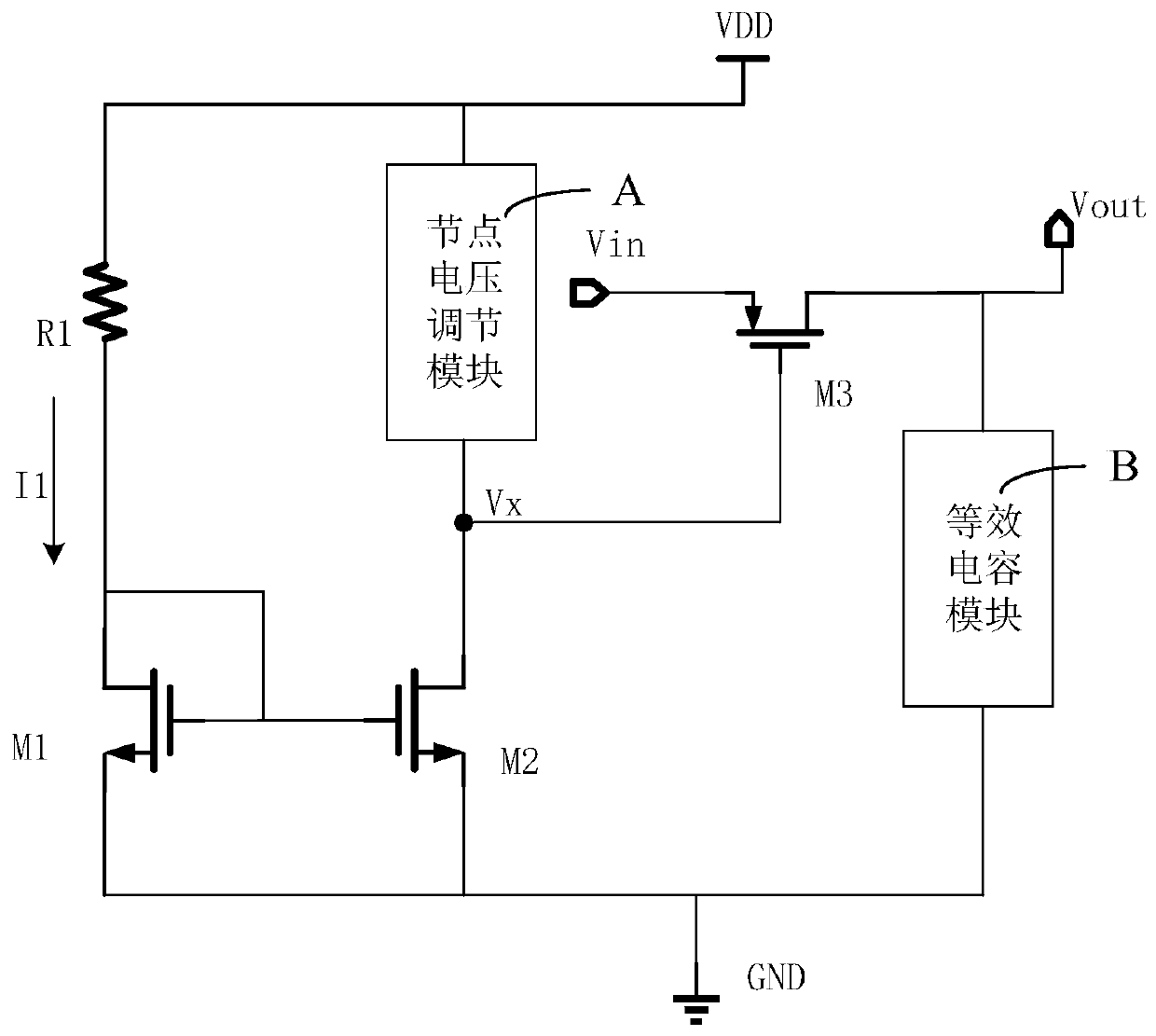
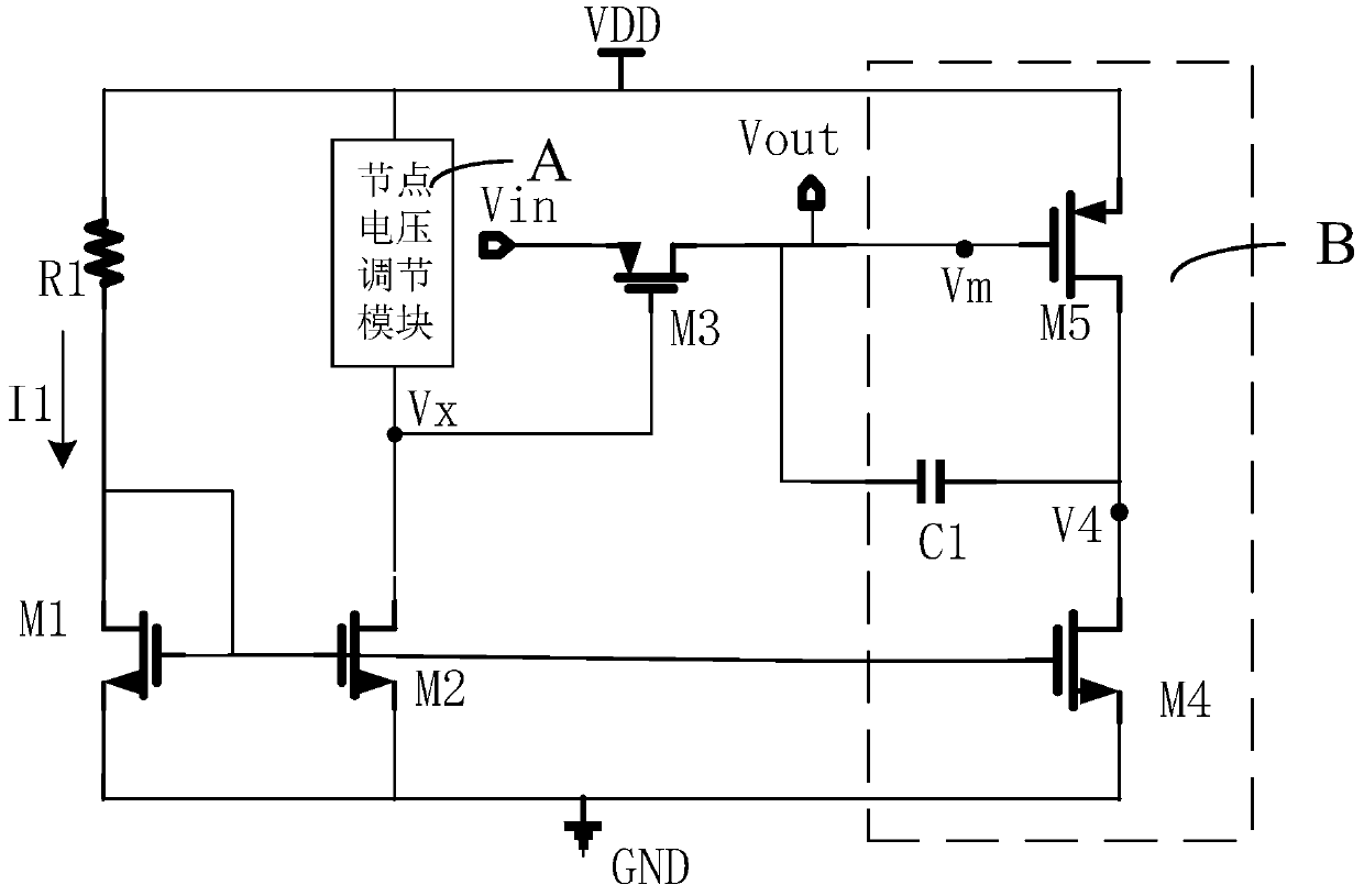
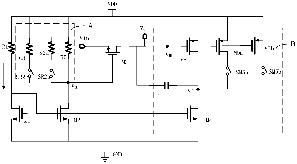
[0021] Such as figure 1 As shown, the present application provides a low-pass filter circuit, the circuit includes a first resistor R1, a first switch M1, a second switch M2, a node voltage adjustment module A, a third switch M3 and an equivalent capacitance module B ;

[0022] The first resistor R1 and the first switch tube M1 form a bias current generating unit, one end of the bias current generating unit is connected to the power supp...


PUM


Abstract

The invention relates to a low-pass filter circuit, a low-pass filter and a CMOS chip. The low-pass filter circuit comprises a first resistor, a first switch tube, a second switch tube, a node voltageadjusting module A, a third switch tube and an equivalent capacitor module B; bias current is generated through the first resistor and the first switching tube; a current mirror structure is formed by the first switch tube and the second switch tube, and the current flowing through the second switch tube is equal to the bias current. The node voltage adjusting module A adjusts the node voltage between the input end of the second switch tube and the control end of the third switch tube, so that the conduction voltage of the third switch tube is increased, large resistance is formed, and the-3dB frequency of the low-pass filter circuit can be effectively increased.. Devices in the low-pass filter circuit can be directly made on an integrated circuit, and low-cost mass production is facilitated.

Description

technical field [0001] The present application relates to the field of analog circuits, in particular to low-pass filter circuits, low-pass filters and CMOS (Complementary Metal Oxide Semiconductor, Complementary Metal Oxide Semiconductor) chips. Background technique [0002] In the field of analog circuits, it is usually necessary to perform low-pass filtering on the input signal, that is, to filter out high-frequency components in the signal. [0003] At present, the commonly used low-pass filter is a first-order passive low-pass filter composed of a resistor and a capacitor. The first-order passive low-pass filter is composed of a resistor R and a capacitor C. The low-pass filter The input terminal is connected to the output terminal through a resistor, the capacitor is connected to one end of the resistor, and the other end is grounded. An important performance indicator describing the filter is the -3dB frequency, which is the frequency corresponding to when the power ...

Claims


Application Information

Patent Timeline
IPC IPC(8): H03H11/12
CPCH03H11/1213Y02E40/40
Inventor 何力
Owner HUNAN GOKE MICROELECTRONICS
Why Eureka
Try Eureka