
Pipeline inner wall cleaning machine

A technology for cleaning machines and pipes, which is applied in the field of cleaning devices and pipe inner wall cleaning machines, and can solve problems such as large residue, low efficiency, and large scale

Active Publication Date: 2021-04-02
徐州华显凯星信息科技有限公司
View PDF2 Cites 0 Cited by
  • Summary
  • Abstract
  • Description
  • Claims
  • Application Information

AI Technical Summary

Problems solved by technology

[0002] At present, in the process of thermal power generation, waste heat is usually used for heating, and high-pressure steam is used for heat transmission and heating. Due to water quality problems, after long-term and long-distance transmission, the inner wall of the pipe will be deposited and attached to the pipe. On the wall, and gradually grow, seriously affecting the flow section of the pipeline, serious blockage and other situations will occur, increasing the transmission resistance of the fluid in the pipeline, greatly reducing the distance of steam transmission, the existing pipeline cleaning is through a single Cleaning is done in a directional cleaning method, and the dirt after cleaning is not discharged in a concentrated manner. The residual amount after cleaning is large, and for the more stubborn scale, it needs to be washed repeatedly from two directions. It is difficult for the existing cleaning device to achieve the washing effect on both sides. , in some mechanical cleaning methods, the pipeline robot enters to clean the scale in the pipeline. Due to the mechanical structure, it is easy to get stuck and wear, which is easy to cause other problems
[0003] Publication number CN106623290A discloses a pipeline cleaning mechanism, which belongs to the technical field of cleaning equipment, and includes a driving mechanism. The output end of the driving mechanism is provided with a rotating mechanism, and the output end of the rotating mechanism is provided with a cleaning mechanism. Cleaning unit, the cleaning unit is located on the same straight line, the cleaning unit includes a fixed block, the outside of the fixed block is provided with a cleaning brush, the device is cleaned through the selection of the mechanical structure, and there is no allowance for variable diameter in the rotation, for the scale forming a thin-walled structure , it is difficult to clean quickly, it is easy to get stuck, and there are residues in cleaning
[0004] Publication number CN208195143U discloses a thermal pipeline dirt cleaning device, a control panel is installed on the side of the water tank, a storage battery is fixedly installed inside the battery box, a microprocessor is provided above the storage battery, a water inlet is provided on the top of the water tank, and one side of the water inlet is A stirring motor is fixedly installed, and the stirring motor is connected to the water tank through a gear column. A heat pump is fixedly installed on the opposite side of the side where the battery box is located. Cleaning through chemical reaction combined with mechanical structure, and dissolving scale parts through corrosion, but due to the large scale, the dissolution time is long, and when the scale and the pipe wall are attached, it needs to wait for penetration, which is inefficient

Method used


Image

  • Pipeline inner wall cleaning machine
  • Pipeline inner wall cleaning machine
  • Pipeline inner wall cleaning machine

Examples


Embodiment 1

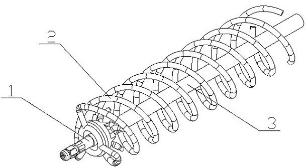
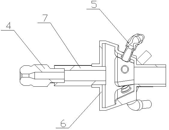
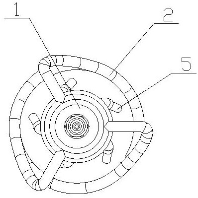
[0026] The pipeline inner wall cleaning machine of the present invention is composed of a cleaning head (1), a slag discharge structure (2) and a water delivery pipe (3). connected, the drainage structure is placed on the cleaning head (1), the slag discharge structure (2) extends to the side of the water delivery pipe (3), the water delivery pipe (3) is a hose, and the cleaning head (1) It consists of a broken wall nozzle (4), a side flushing nozzle (5), a nozzle assembly (6) and an extension tube (7). The nozzle assembly (6) is a hollow circular platform structure, and the two ends of the circular platform are provided with connecting threads One end of the extension tube (7) is screwed and placed in the threaded sleeve at the large end of the round table, and the wall-breaking nozzle (4) is placed at the other end of the extension tube (7). The internal channel of the wall-breaking nozzle (4) is a variable-diameter structure. The side of the nozzle assembly (6) is provided ...

Embodiment 2

[0035] The difference between Embodiment 2 and Embodiment 1 is that the nozzle on the side flushing nozzle (5) is a special-shaped nozzle (13). The cutting ability of the jet stream can clean and wash the scale (12) in a large area, and improve the cleaning efficiency of the scale (12), which is better than the columnar jet flushing effect;

Embodiment 3

[0037]The difference between embodiment 3 and embodiment 1 is that there are two groups of lateral flushing nozzles (5), and the distribution directions of the two groups of lateral nozzles are opposite to each other, so that the scale (12) can be supplemented from the outside when extending in. The scouring increases the scouring area of ​​the outer surface, and the stubborn scale (12) is cleaned and washed multiple times through the reciprocating movement to increase the cleaning effect.


PUM


Abstract

The invention provides a pipeline inner wall cleaning machine. A wall-breaking spray head is used for carrying out high-pressure spraying along the advancing direction, reversed cleaning spray heads are arranged along the wall-breaking spray head in an annular manner, the wall-breaking spray head and the reversed cleaning spray heads are combined to carry out scale deposit cleaning, and are matched with a slag discharging structure to carry out outer discharge. The machine is characterized in that, the machine comprises a cleaning head, a discharging structure and a water conveying pipe, wherein the cleaning head is arranged on the water conveying pipe and is communicated with the water conveying pipe, a water discharging structure is arranged on the cleaning head, the discharging structure extends towards one side of the water conveying pipe, the water conveying pipe is a hose, the cleaning head is composed of the wall-breaking spray head, lateral flushing spray heads, a spray head assembly and an extension tube, the spray head assembly is of a hollow circular truncated cone structure, the two ends of the circular truncated cone are provided with connected threaded sleeves, one end of the extension tube is in threaded connection with the inside of a threaded sleeve at the large end of the circular truncated cone, the wall-breaking spray head is arranged at the other end of theextension tube, the inner channel of the wall-breaking spray head is of a variable-diameter structure, so that wall-breaking and dredging can be carried out for a thin wall formed by water scale.

Description

technical field [0001] The invention relates to a pipeline inner wall cleaning machine, which relates to a cleaning device for cleaning and discharging scale formed due to the adhesion of calcium precipitates in water in a heat transmission pipeline, and belongs to the field of pipeline engineering. In particular, it relates to a cleaning device that utilizes wall-breaking nozzles for high-pressure jetting along the forward direction and circularly distributed reverse cleaning nozzles along the broken-wall nozzles for combined scale cleaning, and cooperates with a slag discharge structure for external discharge. Background technique [0002] At present, in the process of thermal power generation, waste heat is usually used for heating, and high-pressure steam is used for heat transmission and heating. Due to water quality problems, after long-term and long-distance transmission, the inner wall of the pipe will be deposited and attached to the pipe. On the wall, and gradually...

Claims


Application Information

Patent Timeline
IPC IPC(8): B08B9/032B08B9/051
CPCB08B9/0321B08B9/051
Inventor 不公告发明人
Owner 徐州华显凯星信息科技有限公司
Learn More