Energy imaging method, device, equipment and storage medium
An imaging method and energy technology, applied in the field of X-ray imaging, can solve the problems of large scanning dose and large patient damage, and achieve the effect of reducing the scanning dose
- Summary
- Abstract
- Description
- Claims
- Application Information
AI Technical Summary
Problems solved by technology
Method used
Image

Examples
Embodiment 1
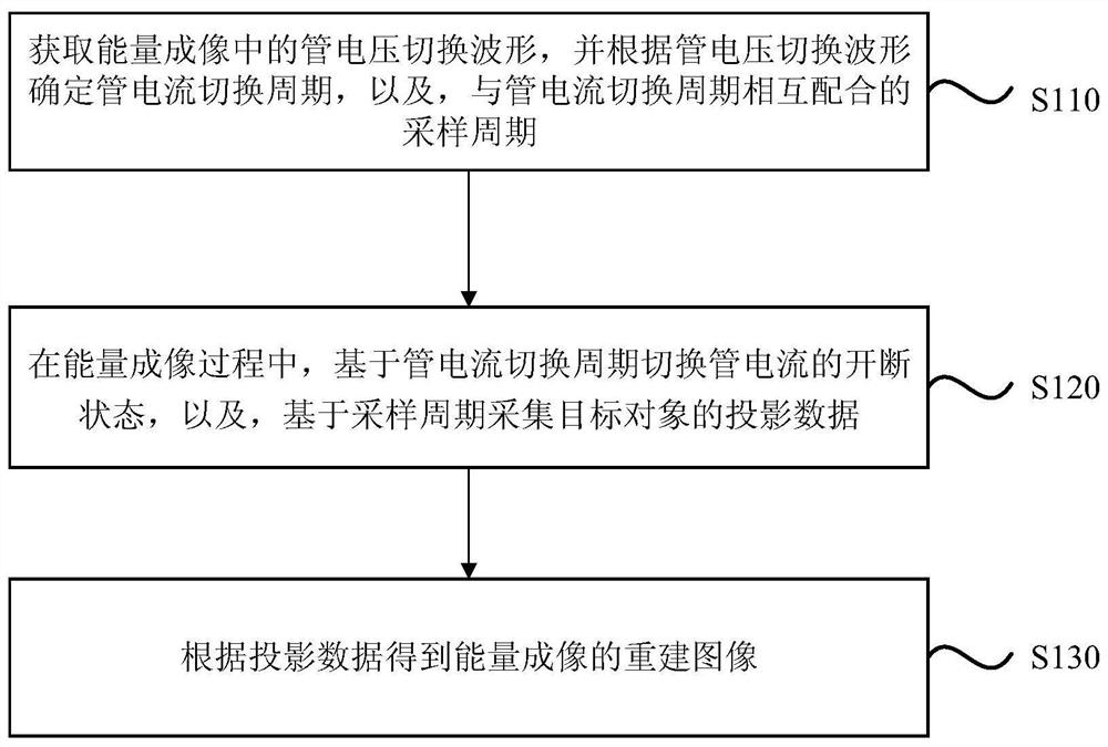
[0058] figure 1 This is a flowchart of an energy imaging method provided in Embodiment 1 of the present invention. This embodiment is applicable to the case of energy imaging, especially to the case of realizing energy imaging with a lower scanning dose. The method may be performed by the energy imaging apparatus provided in the embodiment of the present invention, and the apparatus may be implemented by means of software and / or hardware, and the apparatus may be integrated on various user equipments.
[0059] see figure 1 , the method of the embodiment of the present invention specifically comprises the following steps:
[0060] S110. Acquire the tube voltage switching waveform in the energy imaging, and determine the tube current switching period according to the tube voltage switching waveform, and the sampling period that cooperates with the tube current switching period.
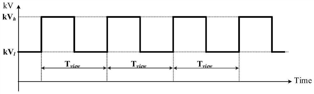
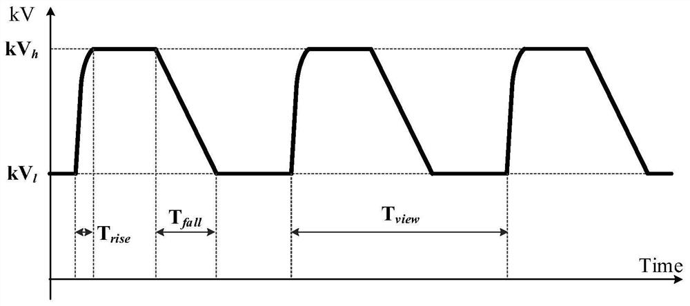
[0061] Among them, in practical applications, limited by the actual physical conditions, the tube...
Embodiment 2
[0090] Figure 11 This is a structural block diagram of an energy imaging apparatus provided in Embodiment 2 of the present invention, and the apparatus is configured to execute the energy imaging method provided in any of the foregoing embodiments. The device and the energy imaging methods of the above embodiments belong to the same inventive concept. For details that are not described in detail in the embodiments of the energy imaging device, reference may be made to the above energy imaging method embodiments. see Figure 11 , the apparatus may specifically include: a period acquisition module 310 , a data acquisition module 320 and an image reconstruction module 330 .
[0091] Wherein, the cycle acquisition module 310 is used for acquiring the tube voltage switching waveform in the energy imaging, and determining the tube current switching cycle according to the tube voltage switching waveform, and the sampling cycle cooperating with the tube current switching cycle;
[...
Embodiment 3
[0111] Figure 12 A schematic structural diagram of a device provided in Embodiment 3 of the present invention, such as Figure 12 As shown, the device includes a memory 410 , a processor 420 , an input device 430 and an output device 440 . The number of processors 420 in the device may be one or more, Figure 12 Take a processor 420 as an example in the above; the memory 410, the processor 420, the input device 430 and the output device 440 in the device can be connected through a bus or other means, Figure 12 Take the connection through the bus 450 as an example.
[0112] As a computer-readable storage medium, the memory 410 can be used to store software programs, computer-executable programs, and modules, such as program instructions / modules corresponding to the energy imaging method in the embodiment of the present invention (for example, the periodic acquisition in the energy imaging device). module 310, data acquisition module 320 and image reconstruction module 330)...
PUM
 Abstract
Description
Claims
Application Information
 - R&D
- Intellectual Property
- Life Sciences
- Materials
- Tech Scout
- Unparalleled Data Quality
- Higher Quality Content
- 60% Fewer Hallucinations
Browse by: Latest US Patents, China's latest patents, Technical Efficacy Thesaurus, Application Domain, Technology Topic, Popular Technical Reports.
© 2025 PatSnap. All rights reserved.Legal|Privacy policy|Modern Slavery Act Transparency Statement|Sitemap|About US| Contact US: help@patsnap.com