
Rope-rod combined driving type rocking-turn mechanism for steel smelting furnace

A hybrid drive and steelmaking furnace technology, applied in the manufacture of converters, etc., can solve the problems of poor mixing performance of molten iron and alloy materials, large reversing tilting impact torque, poor ability to remove impurities, etc., to achieve compact structure, reduce The impact torque of tilting and reversing, the effect of large working space

Active Publication Date: 2019-09-10
YANSHAN UNIV
View PDF6 Cites 1 Cited by
  • Summary
  • Abstract
  • Description
  • Claims
  • Application Information

AI Technical Summary

Problems solved by technology

Because this type of tilting mechanical equipment only tilts with one degree of freedom, the impact moment of the reversing tilting is very large, the mixing performance of molten iron and alloy materials in the furnace is poor, and the ability to remove (hydrogen, phosphorus, carbon, sulfur, gas) and remove impurities is poor. , being scoured by single-degree-of-freedom tilting molten steel for a long time, the life of the converter lining is short

Method used


Image

  • Rope-rod combined driving type rocking-turn mechanism for steel smelting furnace
  • Rope-rod combined driving type rocking-turn mechanism for steel smelting furnace
  • Rope-rod combined driving type rocking-turn mechanism for steel smelting furnace

Examples


Embodiment 1

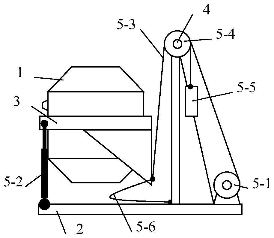
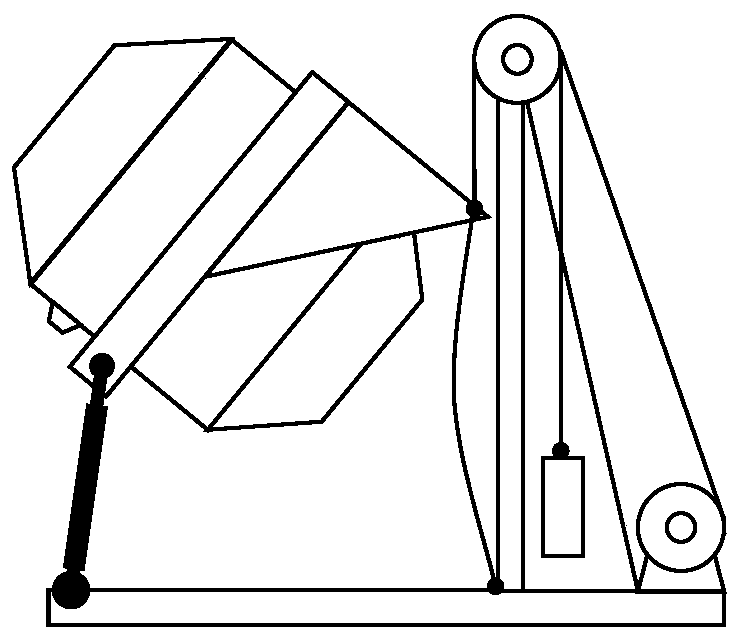
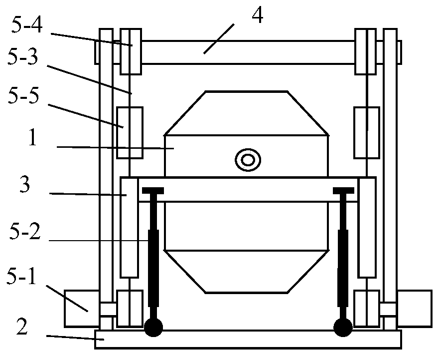
[0027] Further, as Figure 1-3 As shown, the present invention provides a rocking mechanism for a steelmaking furnace driven by a rope-and-rod hybrid drive, including a machine base 2, a moving table 3, a horizontal shaft 4, and two sets of identical rope-and-rod hybrid driving devices; the moving table 3 is provided with a central through hole , the left through hole and the lower right inclined plate tangent to the circumference of the large through hole, the steelmaking furnace 1 is fixedly connected with the central through hole of the moving table 3, and the steel tapping hole of the steelmaking furnace 1 is located at the left through hole side of the moving table 3; The base 2 is a bracket composed of a rectangular horizontal plate and two mutually parallel vertical plates. There are two symmetrical hinge seats on the horizontal plate. The upper and lower ends of the two vertical plates are provided with parallel through holes. The two ends of 4 are fixedly connected wi...


PUM


Abstract

The invention discloses a rope-rod combined driving type rocking-turn mechanism for a steel smelting furnace. The mechanism comprises the steel smelting furnace, a movable platform, a base, two rope-rod combined driving device sets which are structured the same, and a transverse rope, wherein each rope-rod combined driving device set comprises a driving coiling block, a driving rod, a pulling rope, a pulley, a counterweight and a limiting rope; the steel smelting furnace is fixedly connected to the movable platform; the driving rods are hydraulic cylinders or electric cylinders; the pulleys are rotatably connected to a vertical plate of the base through the transverse shaft; the driving coiling blocks are parallel to the transverse shaft, and supporting seats of the driving coiling blocksare fixedly connected to the base; two ends of the driving rods are correspondingly connected to a steel tapping side rotating pair of the movable platform and a ball pair of the base; the middle parts of the pulling ropes are fixedly connected to the other side of the movable platform; two ends of the pulling ropes bypass the same pulley and are correspondingly fixedly connected to the driving coiling blocks and the counterweights; and two ends of the limiting ropes are correspondingly fixedly connected to the base and the other side of the movable platform so as to limit the excessive rotating of the steel smelting furnace. According to the mechanism, the rotating of two driving coiling blocks and the telescoping movement of two driving rods are equal to accurate movement of 2SPS+2SPR parallel mechanisms, and the steel smelting furnace can be subjected to rocking-turn in a plurality of directions, and thus the steel smelting quality is improved, and the service life of the steel smelting furnace is prolonged.

Description

technical field [0001] The invention relates to the technical field of metallurgical equipment, in particular to a rocking mechanism for a steelmaking furnace driven by a rope-rod hybrid drive. Background technique [0002] The combination of steelmaking converter and oxygen lance blowing is one of the main equipments for steelmaking at home and abroad. At present, most of the existing steelmaking converters at home and abroad use one-degree-of-freedom tilting mechanical equipment to drive the converter to tilt through the support ring. The tilting mechanical equipment is driven by multiple AC variable frequency motors, and the multiple motors are in the form of multi-point meshing full suspension, and the torque is balanced through the torsion bar device. Because this type of tilting mechanical equipment only tilts with one degree of freedom, the impact moment of the reversing tilting is very large, the mixing performance of molten iron and alloy materials in the furnace i...

Claims


Application Information

Patent Timeline
IPC IPC(8): C21C5/50
CPCC21C5/50
Inventor 路懿路扬章震叶妮佳
Owner YANSHAN UNIV
Learn More