Novel vacuum foam-plastic hydraulic molding machine with double-rod oil cylinders

A molding machine and oil cylinder technology, which is applied in the field of new double-rod oil cylinder vacuum foam plastic hydraulic molding machine, can solve the problems of inconvenient mold installation, increased enterprise cost, and easy deformation of the oil cylinder, so as to achieve convenient mold height adjustment, improve production efficiency, Guaranteeing the effect of accuracy

Pending Publication Date: 2019-08-30
杭州阿司特智能机械有限公司
View PDF0 Cites 4 Cited by
  • Summary
  • Abstract
  • Description
  • Claims
  • Application Information

AI Technical Summary

Problems solved by technology

Existing vacuum foam plastic hydraulic molding machines are mainly of a single cylinder structure, and the mold is driven by the cylinder to move the mold closer to the solid mold to form a mold. In order to ensure the demoulding of the product, the distance between the solid mold and the mold is generally large, resulting in The expansion radius of the oil cylinder makes the oil cylinder easy to deform during use
At the same time, the fixed mold and the movable mold of the existing vacuum foam plastic hydraulic molding machine are all integral structures. The mold and the mold frame have higher requirements on the process during manufacturing, and it is difficult to process. At the same time, the mold is inconvenient to install. Calibration is difficult, and it takes a lot of time to adjust and try the mold; at the same time, the mold clamping method is extremely complicated, and the clamping speed is slow. The state of maintaining pressure virtually increases the cost of the enterprise, so it is urgent to adjust the existing mold installation method and clamping method to make the mold installation more convenient and improve the production efficiency of the equipment

Method used


Image

  • Novel vacuum foam-plastic hydraulic molding machine with double-rod oil cylinders
  • Novel vacuum foam-plastic hydraulic molding machine with double-rod oil cylinders
  • Novel vacuum foam-plastic hydraulic molding machine with double-rod oil cylinders

Examples


Embodiment Construction

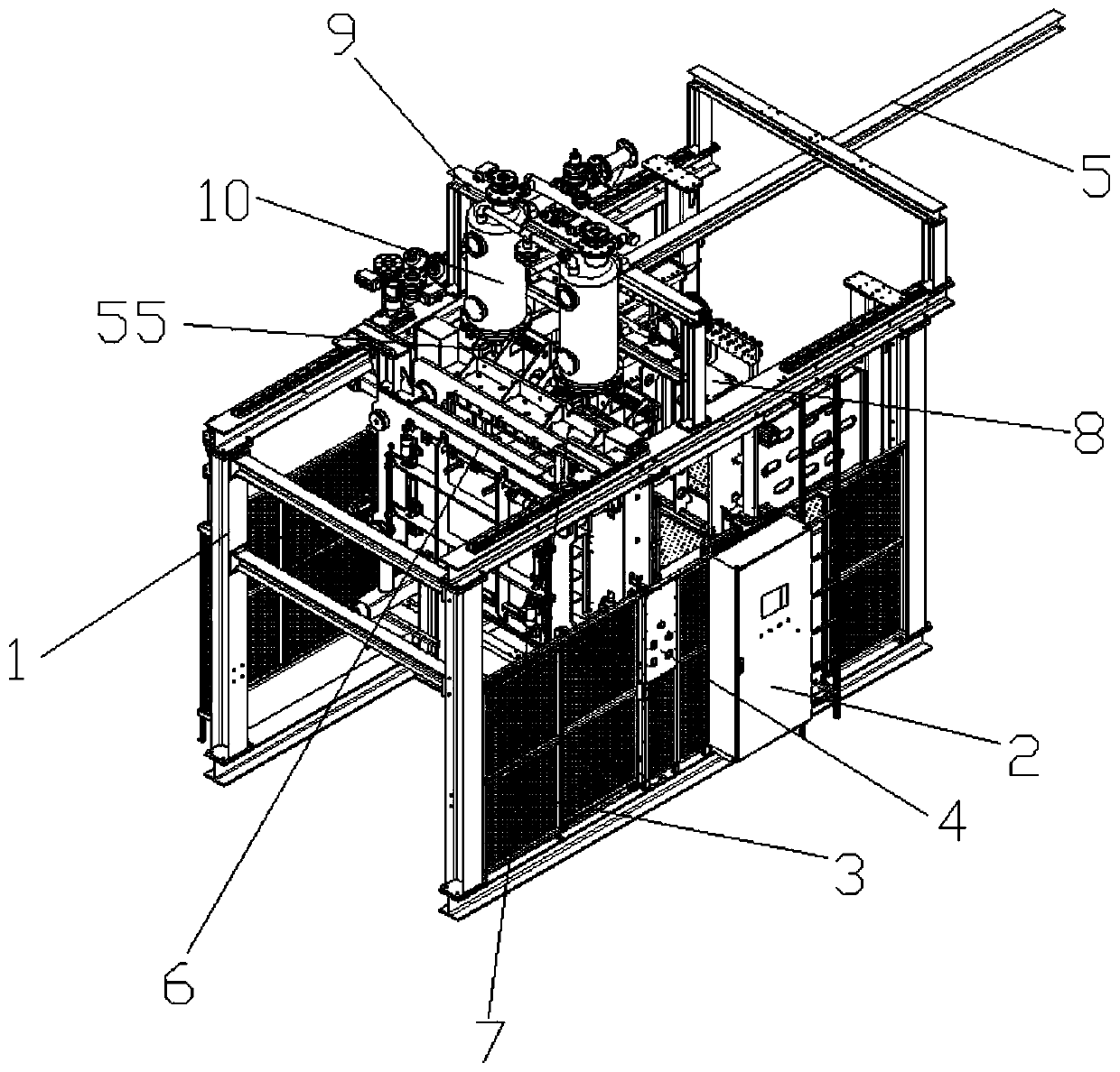
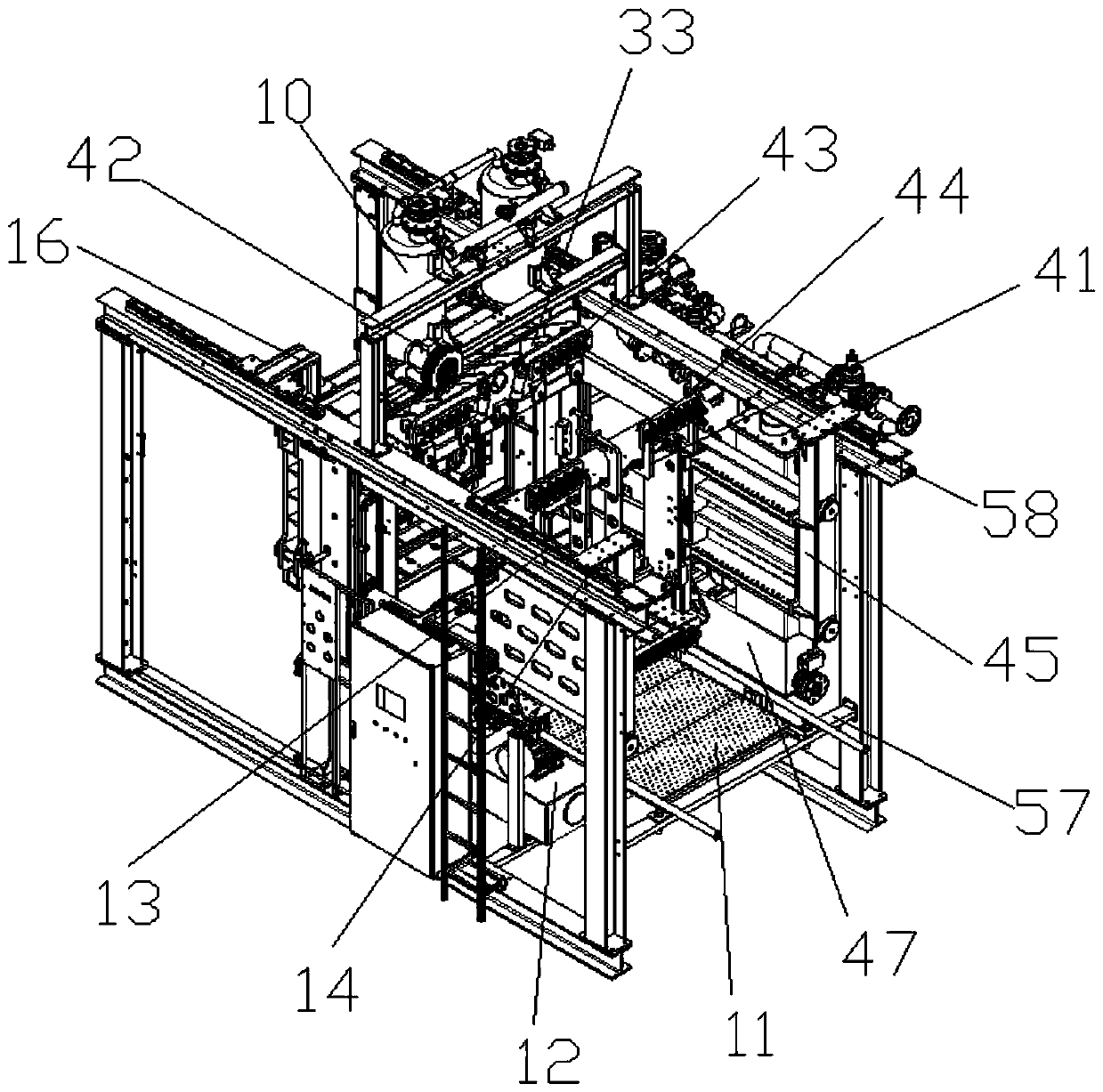
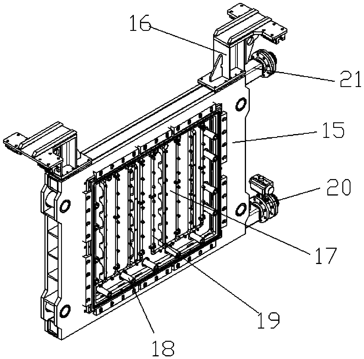
[0053] refer to Figure 1 to Figure 9 A new double-rod oil cylinder vacuum foam plastic hydraulic molding machine is shown, including a frame 1, an electric control cabinet 2, a protective net 3, an instrument panel 4, a stripping plate sliding part 5, a moving mold assembly 6, and a solid mold assembly 7 , mold frame 8, hydraulic oil tank 12, fast loading frame 45, condenser 47 and motor 54, motor 54 is installed on the hydraulic oil tank 12, and hydraulic oil tank 12 is arranged on the lower end of frame 1 inside, and the upper end of hydraulic oil tank 12 is provided with An anti-skid plate 11, the protective net 3 is arranged on both sides of the frame 1, the electric control cabinet 2 and the instrument panel 4 are installed on the frame 1, and the mold moving assembly 6 includes a mold moving frame 15, a mold moving slider The connecting plate 16 and the mold-moving heat insulation board 17, one side of the mold-moving mold frame 15 is provided with a mold-moving intake ...


PUM


Abstract

The invention discloses a novel vacuum foam-plastic hydraulic molding machine with double-rod oil cylinders. The novel vacuum foam-plastic hydraulic molding machine comprises a rack, an electric control cabinet, an instrument panel, a moving mold assembly, a fixed mold assembly, a mold mounting rack, a hydraulic oil tank, a rapid mounting rack, a condenser and a motor. The motor is mounted on thehydraulic oil tank. The moving mold assembly comprises a moving mold frame, a moving mold sliding block connecting plate and a moving mold heat isolation plate. A moving mold air inlet pipe and a moving mold drainage pipe are arranged on one side of the moving mold frame. Mold connecting rods and a moving mold steam outlet are mounted on the moving mold heat isolation plate. The moving mold frameis connected with the rack through the moving mold sliding block connecting plate. The fixed mold assembly comprises a fixed mold frame and a fixed mold fixed plate. The fixed mold frame is fixed to the rack through the fixed mold fixed plate. The two double-rod oil cylinders are mounted on the two sides of the fixed mold frame correspondingly. Piston rods of the double-rod oil cylinders are connected with the moving mold frame and the rapid mounting rack. Mold mounting is convenient, mold locking can be rapidly completed after mounting, automatic production is achieved, production efficiencyis high, and manufactured vacuum foam plastic is good in quality and uniform in size and density.

Description

technical field [0001] The invention relates to a novel double-rod oil cylinder vacuum foam plastic hydraulic forming machine. Background technique [0002] Vacuum foam plastic hydraulic molding machine is mainly used for the production of vacuum foam plastic particles such as EPS, EPP, ETPU, etc., by adding foaming agent to polystyrene resin, and then softening by heating, gas is generated, and a hard closed cell is formed. Structural foam plastic. Existing vacuum foam plastic hydraulic molding machines are mainly of a single cylinder structure, and the mold is driven by the cylinder to move the mold closer to the solid mold to form a mold. In order to ensure the demoulding of the product, the distance between the solid mold and the mold is generally large, resulting in The expansion radius of the oil cylinder makes the oil cylinder easy to deform during use. At the same time, the fixed mold and the movable mold of the existing vacuum foam plastic hydraulic molding machin...

Claims


Application Information

Patent Timeline
Patent Type & Authority Applications(China)
IPC IPC(8): B29C44/02B29C44/34B29C44/60B29C44/58B29C33/20
CPCB29C33/20B29C44/02B29C44/3403B29C44/58B29C44/60
Inventor 孝希军
Owner 杭州阿司特智能机械有限公司
Why Eureka
Try Eureka