Mountain area highway subgrade and construction method
A technology for roadbeds and roads, which is applied to roads, roads, and the bottom of roads, etc. It can solve the problems of low drainage capacity and easy blockage, and achieve the effects of preventing rainwater retention, protecting roadbeds, and increasing drainage performance
- Summary
- Abstract
- Description
- Claims
- Application Information
AI Technical Summary
Problems solved by technology
Method used
Image
Examples
Embodiment 1
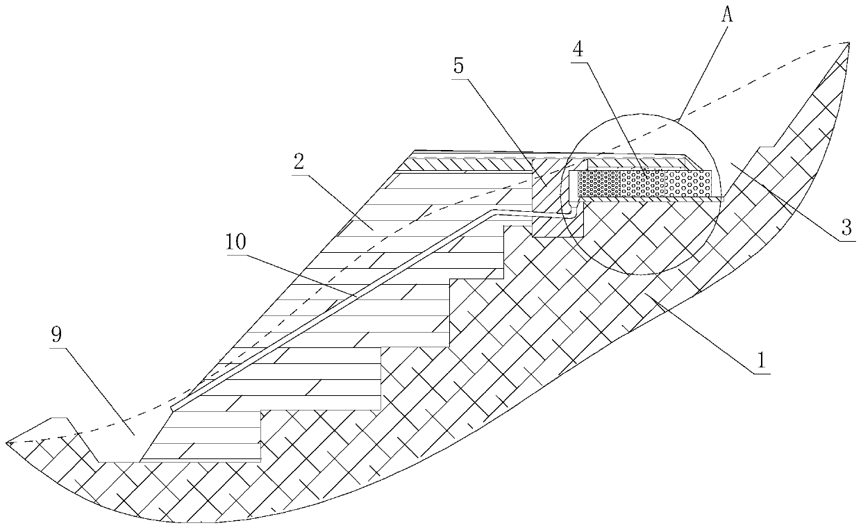
[0033] A roadbed for a mountainous road, comprising an excavated embankment 1 and a filled embankment 2, where a main drainage ditch 3 is built at the connection between the excavated embankment 1 and the mountain body. The top of the excavated subgrade 1 is provided with several columns of bin grid boxes 4, and the bin grid boxes 4 are arranged from the inside of the main drainage ditch 3 to the excavated subgrade 1, that is, the bin grid boxes 4 are arranged in several columns along the length of the road. It can be understood that the bin grid box 4 is made for filling stones in the gabion net, and most of them are filled with cobblestones with a compression resistance of 60mPa or more. The top of the excavated subgrade 1 described in the Binger grid box 4 is facing the filling subgrade 2 side and is vertically built with a concrete ridge 5, that is to say, the Binger grid box 4 is located at the inner side of the concrete ridge 5 and surrounded by the side walls of the main...
Embodiment 2
[0040] Based on Embodiment 1, a siphon pipe 10 is provided inside the fill roadbed 2 . It should be understood that the water inlet of the siphon pipe 10 is located between the concrete ridge 5 and the bin grid box 4 , and the water outlet of the siphon pipe 10 extends to the auxiliary drainage ditch 9 . Arranged in this way, when the amount of water to be discharged is too large, rainwater can be discharged from the main drainage ditch 3 and the auxiliary drainage ditch 9 at the same time, thereby reducing the drainage pressure of the main drainage ditch 3 . The siphon 10 can accelerate the discharge of rainwater, prevent rainwater from stagnating, and ensure the safety of the roadbed. Wherein, the siphon pipe 10 can generate negative pressure through flow velocity difference to achieve siphon effect, such as an inverted L-shaped pipeline; it can also be a pipeline in which pre-tank water diversion generates negative pressure to achieve siphon effect, such as an inverted S-sh...
Embodiment 3
[0043] Based on embodiment 1 or embodiment 2, in order to eliminate the compaction blind area of filling subgrade 2, improve the compactness of filling subgrade 2 and the overall stability of the subgrade, the junction of described excavating subgrade 1 and filling subgrade 2 is dug as a ladder shape. And for improving the stability of concrete ridge 5, described concrete ridge 5 bottoms are embedded in the excavated subgrade 2 upper ends.
[0044] In addition, because most roads in mountainous areas have a certain slope, the rainwater received by the road will flow down the road, and finally flow out from the side slope of the roadbed or the drainage ditch. In this embodiment, the road surface structure layer 7 is inclined to the side of the main drainage ditch 3. On the one hand, it can make the rainwater on the road flow to the main drainage ditch 3, preventing rainwater from accumulating and affecting driving safety. On the other hand, it can prevent road surface water ...
PUM
 Abstract
Description
Claims
Application Information
 - R&D
- Intellectual Property
- Life Sciences
- Materials
- Tech Scout
- Unparalleled Data Quality
- Higher Quality Content
- 60% Fewer Hallucinations
Browse by: Latest US Patents, China's latest patents, Technical Efficacy Thesaurus, Application Domain, Technology Topic, Popular Technical Reports.
© 2025 PatSnap. All rights reserved.Legal|Privacy policy|Modern Slavery Act Transparency Statement|Sitemap|About US| Contact US: help@patsnap.com


