
Laser scanning mirror plane cleaning device for material field

A laser scanning and cleaning device technology, applied in the cleaning method using tools, the cleaning method using gas flow, cleaning flexible objects, etc., can solve the problems that the scanning work cannot be performed normally, the laser is easily blocked by dust, etc., and delay hardening Phenomenon, avoid hardening phenomenon, reduce the effect of water vapor content

Inactive Publication Date: 2019-08-23
HUANENG LAIWU POWER GENERATION CO LTD +1
View PDF17 Cites 2 Cited by
  • Summary
  • Abstract
  • Description
  • Claims
  • Application Information

AI Technical Summary

Problems solved by technology

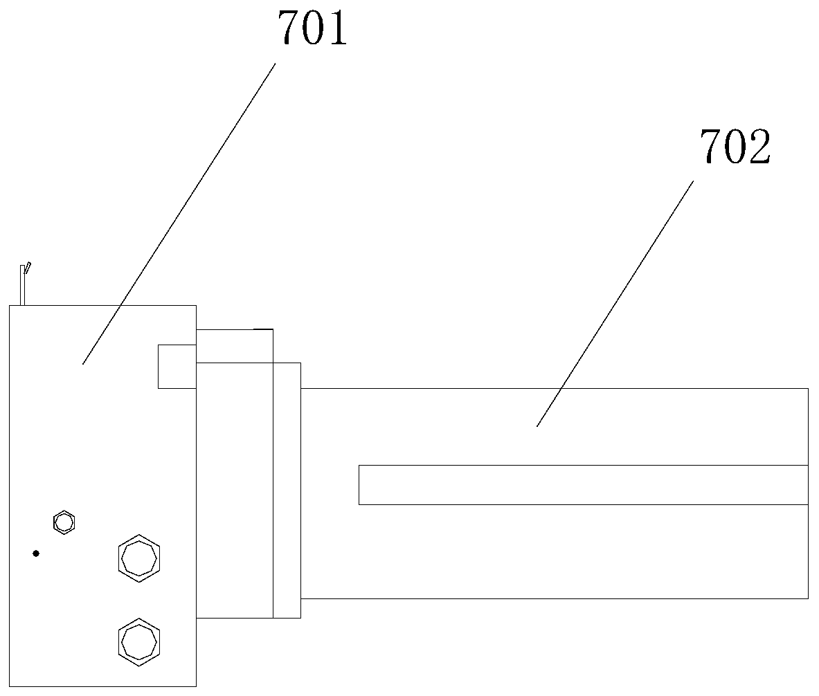
[0004] The main purpose of this application is to provide a laser scanning mirror cleaning device for stockyards to solve the problem that the laser scanning coal in the power plant is easily blocked by dust and cannot perform normal scanning work

Method used


Image

  • Laser scanning mirror plane cleaning device for material field
  • Laser scanning mirror plane cleaning device for material field
  • Laser scanning mirror plane cleaning device for material field

Examples


Embodiment Construction

[0021] In order to enable those skilled in the art to better understand the solution of the present application, the technical solution in the embodiment of the application will be clearly and completely described below in conjunction with the accompanying drawings in the embodiment of the application. Obviously, the described embodiment is only It is an embodiment of a part of the application, but not all of the embodiments. Based on the embodiments in this application, all other embodiments obtained by persons of ordinary skill in the art without creative efforts shall fall within the protection scope of this application.

[0022] It should be noted that the terms "first" and "second" in the description and claims of the present application and the above drawings are used to distinguish similar objects, but not necessarily used to describe a specific sequence or sequence. It should be understood that the data so used may be interchanged under appropriate circumstances for th...


PUM


Abstract

The invention discloses a laser scanning mirror plane cleaning device for a material field. The laser scanning mirror plane cleaning device is arranged on a protective cover on the outer side of a laser scanner and comprises an air heating component for heating water vapor in the air outside the protective cover, an air purging component for purging dust in the air outside the protective cover, amirror plane cleaning component for washing and brushing the outer wall of the protective cover, and a controller, wherein the air heating component and the air purging component are mounted on the outer wall of the protective cover; the mirror plane cleaning component is movably arranged on the outer wall of the protective cover; and the control terminals of the air heating component, the air purging component and the mirror plane cleaning component are electrically connected with the control signal output end of the controller. The laser scanning mirror plane cleaning device solves the technical problem that a laser for scanning coal in a power plant can be shielded by dust easily and cannot carry out scanning operation normally.

Description

technical field [0001] The present application relates to the field of power plant application equipment, in particular, to a laser scanning mirror surface cleaning device for stockyards. Background technique [0002] At this stage, some power plants use an unattended automation system for the acquisition and location of coal materials. The main equipment is the laser scanner in the stockyard. Presented in a three-dimensional form, it provides accurate data support for the unattended system, and also provides accurate data for the inventory of coal materials. However, laser scanning equipment is often polluted by dust in the power plant, which not only affects the accuracy of scanning, but may even fail to scan normally due to the blurring of the laser scanning head. Therefore, it is necessary to install a glass cover on the outside of the laser emitting device For protection, the laser that emits laser light penetrates the glass cover to measure the condition of the coal m...

Claims


Application Information

Patent Timeline
Patent Type & Authority Applications(China)
IPC IPC(8): B08B11/00B08B5/02B08B1/04B01D53/26
CPCB08B11/00B08B5/02B01D53/26B01D2257/80B08B1/32B08B1/12
Inventor 王垚王栩柯波张华东张兰庆杨柏依张林辉董鹏杨富强夏阳夏江勇
Owner HUANENG LAIWU POWER GENERATION CO LTD
Learn More