Pumping voltage detection and discharge circuit

A bleeder circuit, voltage detection technology, applied in battery circuit devices, circuit devices, safety/protection circuits, etc. Comparator circuit is complex and other problems, to achieve the effect of high voltage sampling accuracy, ensuring AD conversion accuracy, and increasing anti-interference ability

Active Publication Date: 2019-08-20
HANGZHOU DIANZI UNIV
View PDF6 Cites 0 Cited by
  • Summary
  • Abstract
  • Description
  • Claims
  • Application Information

AI Technical Summary

Problems solved by technology

[0002] In the frequency conversion speed control system, when the motor suddenly stops or reverses suddenly, the motor is in the state of regenerative braking, and the electric energy regenerated by the motor is fed back to the DC circuit after full-wave rectification by the freewheeling diode. The electric energy cannot be fed back to the grid, resulting in filtering The DC voltage at both ends of the capacitor increases, that is, the pump voltage is generated, which will seriously threaten the safe operation of the motor and cause permanent damage to the power device
[0003] The generation of pump voltage is inevitable during the braking process of the motor. The traditional processing method is composed of a voltage sampling circuit, a Schmitt comparator and a driving circuit. The disadvantages are: 1. The Schmitt comparator circuit is too complicated , It is necessary to obtain the upper and lower threshold voltages through tedious calculations; 2. No isolation is used between the overall circuit and the pumping voltage, which may cause the pumping voltage to interfere with the overall circuit; 3. The driving circuit can only control the MOS tube The complete turn-on and turn-off of the MOS cannot control the partial turn-on and turn-off of the MOS

Method used


Image

  • Pumping voltage detection and discharge circuit

Examples


Embodiment Construction

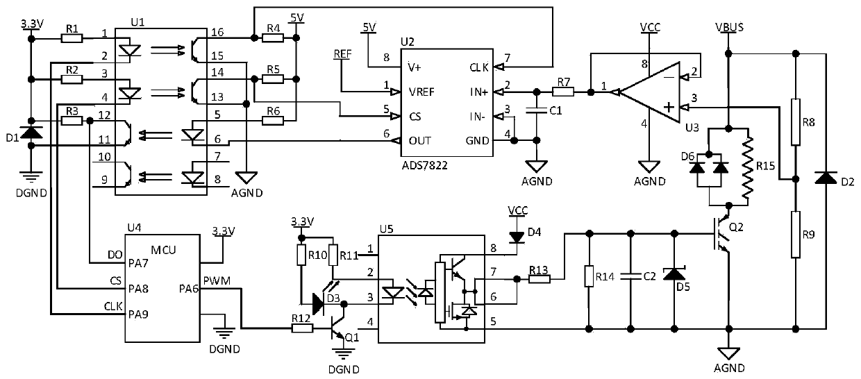
[0014] Such as figure 1 As shown, the present invention comprises single-chip microcomputer U4, voltage sampling circuit, optocoupler isolation circuit and voltage discharge circuit; The model of single-chip microcomputer U4 is STM32F103C8T6;

[0015] The voltage sampling circuit includes an operational amplifier U3, a voltage sampling chip U2, voltage dividing resistors R8, R9, an impedance matching resistor R7, a filter capacitor C1, and a diode D2.

[0016] Among them, one end of the voltage dividing resistor R8 is connected to the power supply VBUS and the cathode of the diode D2, the other end of the voltage dividing resistor R8 is connected to the voltage dividing resistor R9 and the positive input terminal of the operational amplifier U3, and the other end of the voltage dividing resistor R9 is connected to the ground AGND and the anode of the diode D2 are connected, the positive power supply terminal of the operational amplifier U3 is connected to the power supply VCC,...


PUM


Abstract

The invention discloses a pumping voltage detection and discharge circuit. The invention changes the conventional pumping voltage detection and discharge circuit and designs a novel pumping voltage detection and discharge circuit. The circuit can detect the power supply voltage stably and quickly and can filter out the unstable interference in the power supply. The pumping voltage detection and discharge circuit transmits a voltage signal to a single-chip microcomputer through an AD conversion chip and controls the single-chip microcomputer to output a PWM signal to control the interruption ofan MOS transistor, thereby quickly discharging the pumping voltage, and greatly enhancing the stability of the traditional pumping voltage detection and discharge circuit. The pumping voltage detection and discharge circuit disclosed by the invention comprises a single-chip microcomputer U4, a voltage sampling circuit, an optical coupler isolation circuit and a voltage discharge circuit. The circuit has the characteristics of high voltage sampling accuracy, long-time working stability, simple circuit structure, isolation function and simple circuit maintenance.

Description

technical field [0001] The invention relates to a pump-up voltage detection and discharge circuit, which is mainly used for detection and discharge of the pump-up voltage generated by the motor of an electric forklift powered by a storage battery due to emergency stop or reverse rotation. Background technique [0002] In the frequency conversion speed control system, when the motor suddenly stops or reverses suddenly, the motor is in the state of regenerative braking, and the electric energy regenerated by the motor is fed back to the DC circuit after full-wave rectification by the freewheeling diode. The electric energy cannot be fed back to the grid, resulting in filtering The increase of the DC voltage across the capacitor, that is, the generation of a pumped voltage, will seriously threaten the safe operation of the motor and cause permanent damage to the power device. [0003] The generation of pump voltage is inevitable during the braking process of the motor. The trad...

Claims


Application Information

Patent Timeline
IPC IPC(8): H02M1/32H02J7/00
CPCH02J7/0029H02M1/32H02M1/322
Inventor 高明煜汤金迪何志伟杨宇翔曾毓黄继业
Owner HANGZHOU DIANZI UNIV
Why Eureka
Try Eureka