Wire transmission type four-connecting-rod mechanism
A technology of four-bar linkage mechanism and wire transmission, which is applied in the field of mechanical arms, can solve the problems of large friction torque of gravity torque, etc., and achieve the effect of reducing friction torque, reducing joint gravity torque, and reducing output power
- Summary
- Abstract
- Description
- Claims
- Application Information
AI Technical Summary
Problems solved by technology
Method used
Image
Examples
specific Embodiment approach 1
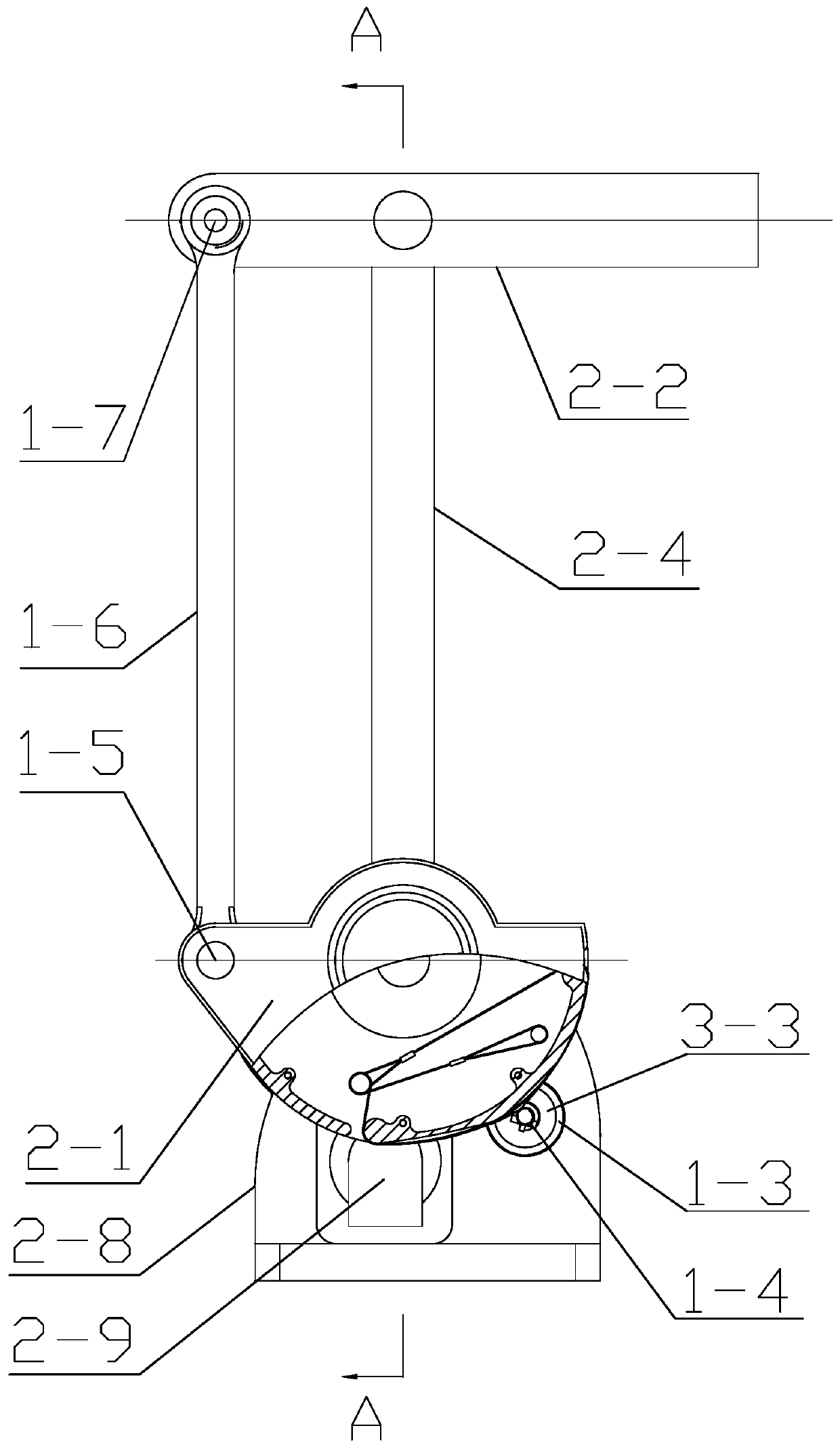
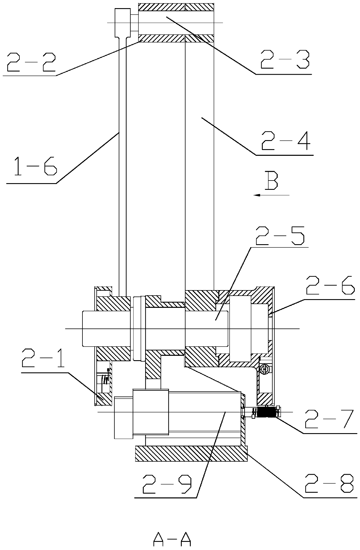
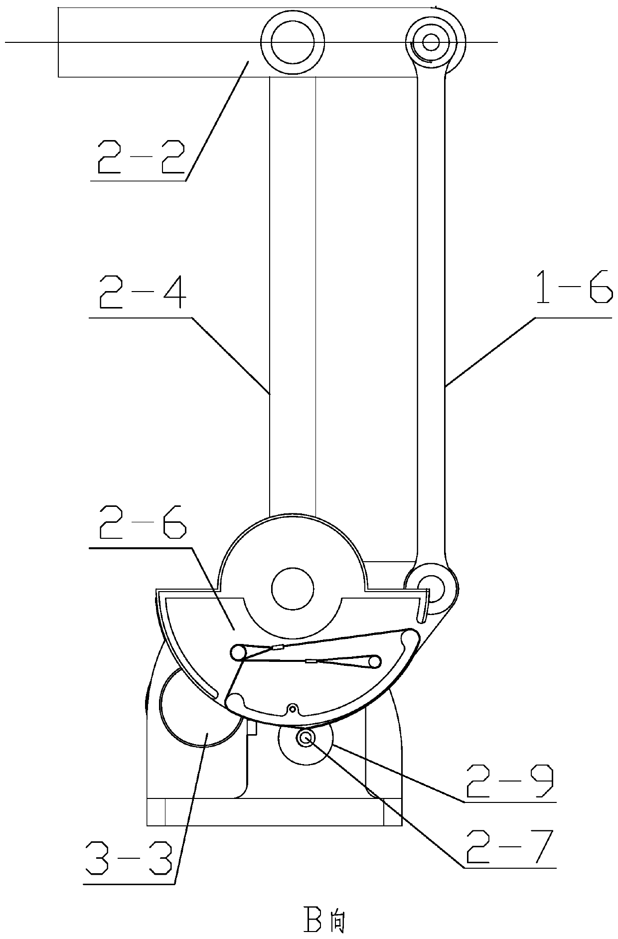
[0023] Specific implementation mode one: combine figure 1 , figure 2 and image 3 Describe this embodiment. In this embodiment, the wire-driven four-bar linkage mechanism includes an elbow motor mount 1-3, an elbow pitch motor 3-3, an elbow link 1-6, and a forearm body 2. -2, large arm body 2-4, shoulder pitching seat 2-8, shoulder pitching motor 2-9, elbow wire transmission deceleration mechanism and shoulder wire transmission deceleration mechanism, elbow pitch motor 3-3 is fixedly installed on On the elbow motor mounting base 1-3, the elbow motor mounting base 1-3 and the shoulder pitching motor 2-9 are jointly fixedly installed on the shoulder pitching seat 2-8, and the elbow pitching motor 3-3 passes through the elbow wire The transmission reduction mechanism drives the elbow connecting rod 1-6 to swing, the shoulder pitch motor 2-9 drives the big arm body 2-4 to swing through the shoulder wire transmission reduction mechanism, and one end of the elbow connecting rod 1...
specific Embodiment approach 2
[0028] Specific implementation mode two: combination Figure 4 Describe this embodiment, the elbow wire drive deceleration mechanism described in this embodiment includes an elbow upper wire 1-1, an elbow lower wire 1-2, an elbow wire drive driving wheel 1-4 and an elbow wire drive disc 2-1, an upper elbow wire fixing column 1-9 and a lower elbow wire fixing column 1-8 are respectively arranged on the board surface of the elbow wire transmission disc 2-1, along which the elbow wire transmission disc 2-1 There is an arc-shaped protrusion on the arc-shaped edge of the arc-shaped protrusion, and there are two gaps on the arc-shaped protrusion, which are respectively the silk gap 2-1-2 at the lower part of the elbow and the silk gap 2-1-1 at the upper part of the elbow, and the upper part of the elbow The wire fixing column 1-9 is set close to the wire gap 2-1-2 at the lower part of the elbow, the wire fixing column 1-8 at the lower elbow is set close to the wire gap 2-1-1 at the ...
specific Embodiment approach 3
[0033] Specific implementation mode three: combination Figure 5 Describe this embodiment, the shoulder wire transmission deceleration mechanism described in this embodiment includes shoulder wire drive disc 2-6, shoulder upper wire 3-2, shoulder lower wire 3-1 and shoulder wire drive drive wheel 2-7,
[0034] A shoulder upper silk fixing column 3-5 and a shoulder lower silk fixing column 3-6 are arranged respectively on the board surface of the shoulder silk driving disk 2-6, along the arc edge of the shoulder silk driving disk 2-6. There is an arc-shaped protrusion at the center, and there are two gaps on the arc-shaped protrusion, which are the wire gap 2-6-2 in the lower part of the shoulder and the wire gap 2-6-1 in the upper part of the shoulder, and the wire fixing column 3 in the upper part of the shoulder. -5 is arranged near the wire gap 2-6-2 at the bottom of the shoulder, and the wire fixing column 3-6 at the bottom of the shoulder is arranged near the wire gap 2-...
PUM
 Abstract
Description
Claims
Application Information
 - Generate Ideas
- Intellectual Property
- Life Sciences
- Materials
- Tech Scout
- Unparalleled Data Quality
- Higher Quality Content
- 60% Fewer Hallucinations
Browse by: Latest US Patents, China's latest patents, Technical Efficacy Thesaurus, Application Domain, Technology Topic, Popular Technical Reports.
© 2025 PatSnap. All rights reserved.Legal|Privacy policy|Modern Slavery Act Transparency Statement|Sitemap|About US| Contact US: help@patsnap.com


