
Simple type bone cutter

A bone crusher and a simple technology, applied in the field of medical devices, can solve the problems of affecting bone healing, long time, and inconvenient use, and achieve the effects of reducing the risk of pollution, short learning curve, and convenient use.

Pending Publication Date: 2019-08-20
SHANGHAI NINTH PEOPLES HOSPITAL SHANGHAI JIAO TONG UNIV SCHOOL OF MEDICINE +1
View PDF4 Cites 0 Cited by
  • Summary
  • Abstract
  • Description
  • Claims
  • Application Information

AI Technical Summary

Problems solved by technology

[0004] However, in the current domestic operation, the obtained bone fragments are mainly bitten into bone fragments of appropriate size with rongeurs. This method takes a long time and is inefficient; the uneven size of the bone fragments affects bone Healing; it may even cause secondary damage caused by sharp edges of bone fragments, thus affecting the surgical effect
In order to solve these problems, some researchers have proposed electric bone crushers, but these instruments require many parts to be sterilized, and often need to be sterilized separately. In this process, the risk of contamination by broken bone particles is increased, and once the contamination occurs and the fusion fails, it will cause serious damage to the patient (application numbers: 201420035965.X, 201420035971.5 and 201710484935.5)
There are also researchers who have proposed a hand-operated bone crusher, but it is not aimed at the bone fragments obtained in spinal surgery, and its volume is relatively large, and it is not easy to use (application number: 200820204245.6)

Method used


Image

  • Simple type bone cutter
  • Simple type bone cutter
  • Simple type bone cutter

Examples


Embodiment Construction

[0025] The technical solutions of the present invention will be further described below in conjunction with the drawings and embodiments.

[0026] In the description of the following specific embodiments, in order to clearly demonstrate the structure and working mode of the present invention, many directional words will be used to describe, but "top", "lower end", "left", "right", " Words such as "outside" and "inside" are to be understood as convenient terms, and should not be understood as restrictive words.

[0027] In the following description of specific embodiments, it should be understood that the terms "upper", "lower", "front", "rear", "left", "right", "vertical", "top", "bottom" ", "inner", "outer" and other indicated orientations or positional relationships are based on the orientations or positional relationships shown in the drawings, which are only for the convenience of describing the present invention and simplifying the description, rather than indicating or i...


PUM


Abstract

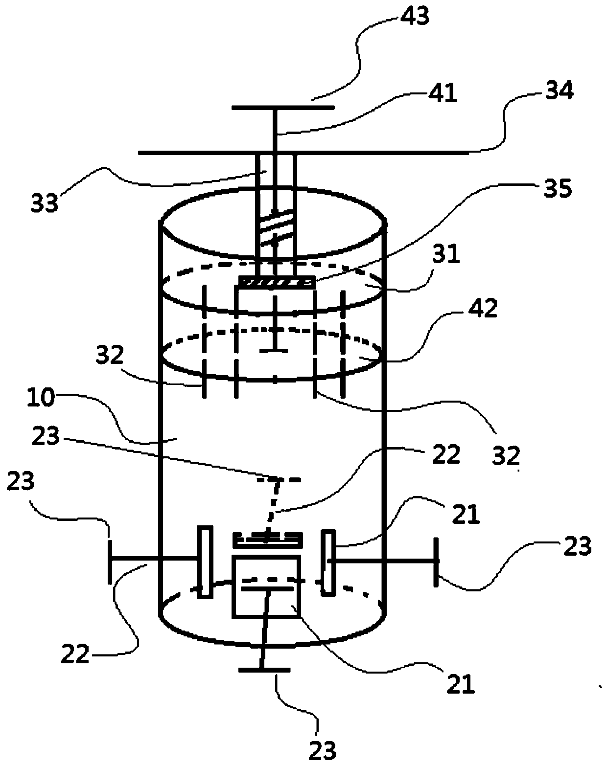
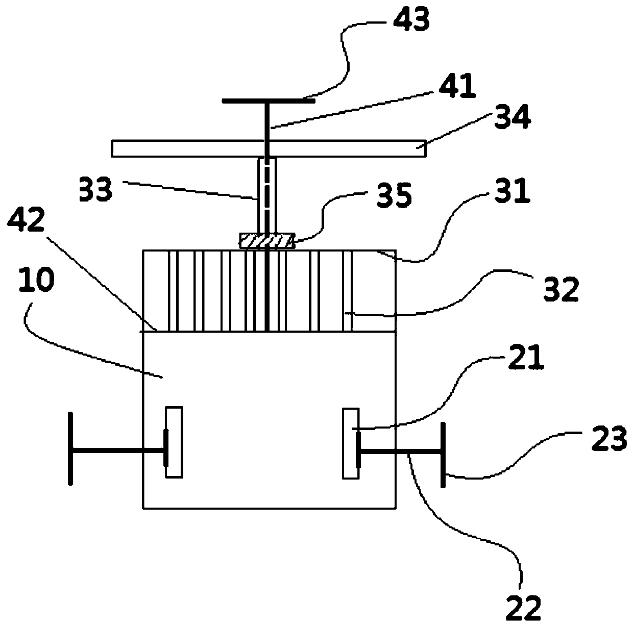
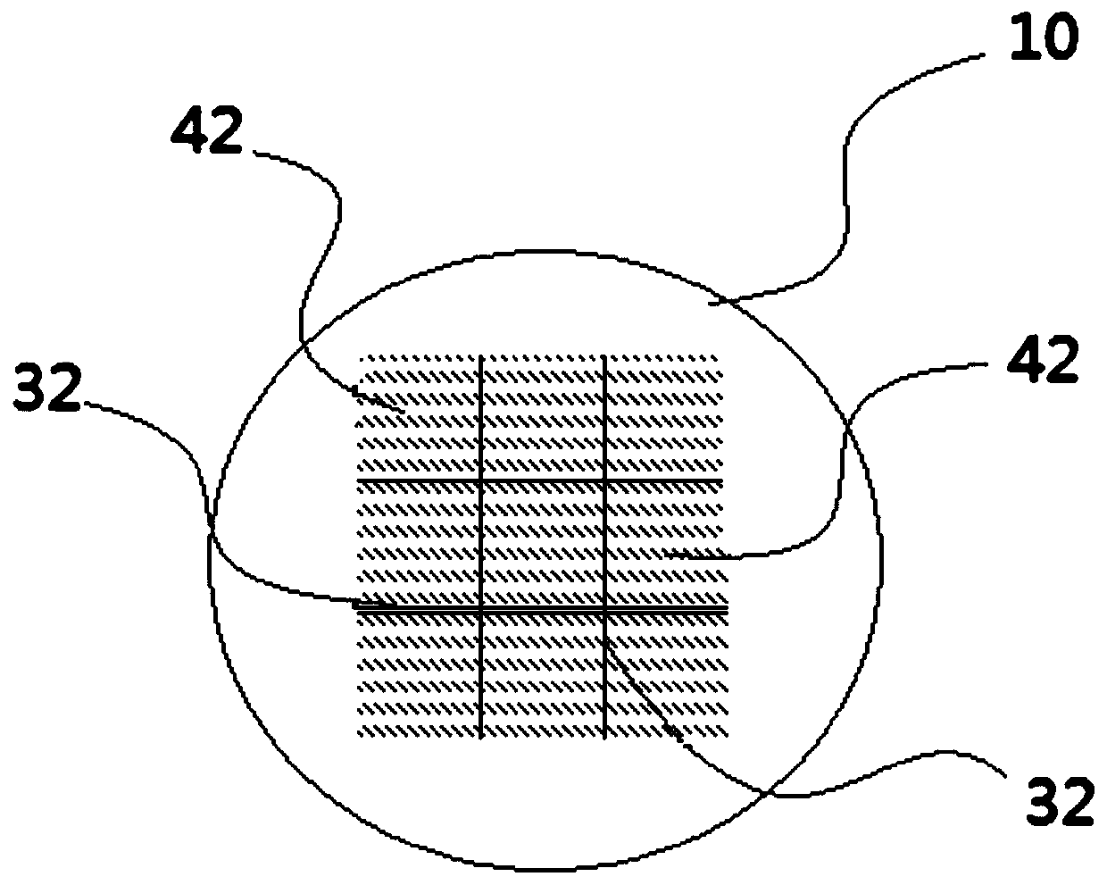
The invention discloses a simple type bone cutter specially designed for spinal surgery. The bone cutter comprises the following parts: a container, wherein at least one pair of second through-holes is symmetrically disposed on the bottom of the container; a fixator installed at the bottom end of the container; a cutting device, wherein the cutting device comprises a cover plate matched with the wall of the container, a knife array disposed on the lower surface of the cover plate, a hollow connecting rod fixedly connected to the cover plate, a rotating handle disposed at the top end of the connecting rod and a force transducer disposed on the hollow connecting rod and located between the rotating handle and the cover plate; and a push device, wherein the push device comprises a push rod, apush plate and a tapping plate disposed at the two ends of the push rod respectively, the push rod is sleeved in the hollow connecting rod and the two ends of the push rod penetrate through the hollow connecting rod, and the push plate can slide longitudinally on the knife array. The bone cutter provided by the invention has a smaller volume and can be disinfected together with a common surgicalinstrument. The bone cutter can reduce the risk of pollution without the need for external power supply. The small bone pieces cut by using the bone cutter are evenly sized for easy transplantation and are especially suitable for spinal surgery.

Description

technical field [0001] The invention belongs to the technical field of medical devices, and in particular relates to a simple bone crusher. Background technique [0002] Autologous bone transplantation is one of the most important surgical techniques in orthopedics, especially in spinal surgery. The main purpose of the bone crusher is to divide the large bone blocks obtained during the operation into small bone particles quickly and easily, so as to facilitate bone transplantation. [0003] As the population ages, the incidence of spinal degenerative diseases such as cervical spondylosis and lumbar disc herniation is increasing. Surgical decompression is usually the ultimate effective treatment for such diseases. Although there are various surgical decompression methods, "spinal canal decompression-internal fixation-spinal fusion" is still the most commonly used surgical method for this type of surgery. Spinal internal fixation can provide good stability in the early stage,...

Claims


Application Information

Patent Timeline
Patent Type & Authority Applications(China)
IPC IPC(8): A61B90/00B02C18/02B02C18/04
CPCA61B90/08B02C18/02B02C18/04
Inventor 孙鑫王金武万克明杨涵戴尅戎
Owner SHANGHAI NINTH PEOPLES HOSPITAL SHANGHAI JIAO TONG UNIV SCHOOL OF MEDICINE
Learn More