
A joint automatic calibration method and device for a robot visual servo system

A technology of robot vision and servo system, applied in the computer field, can solve problems such as global optimization without consideration of system error, error analysis and optimization, and increased debugging difficulty, so as to achieve the effect of eliminating manual operation, realizing system error and realizing automation

Active Publication Date: 2020-03-17
北京无远弗届科技有限公司
View PDF16 Cites 1 Cited by
  • Summary
  • Abstract
  • Description
  • Claims
  • Application Information

AI Technical Summary

Problems solved by technology

[0006] These existing calibration methods mainly focus on the calibration of the traditional visual servo system. If a non-imaging sensor positioning system is introduced into the servo system, it cannot be calibrated with it. That is, the current visual calibration method is limited to narrowly based on The visual servo system of the visible light image sensor; at the same time, there are a lot of manual operations in the traditional calibration method, such as the need to manually move the target or manually operate the robot to move and collect target images in different directions, which will increase the difficulty of debugging in the actual production environment. In addition, because the final error of the visual servo system is accumulated by the errors of multiple calibration processes, most of the current research only analyzes and optimizes the error of a single calibration, without considering the global optimization of the system error

Method used


Image

  • A joint automatic calibration method and device for a robot visual servo system
  • A joint automatic calibration method and device for a robot visual servo system
  • A joint automatic calibration method and device for a robot visual servo system

Examples


Embodiment Construction

[0036] The specific embodiments of the present invention will be further described below in conjunction with the accompanying drawings. The following examples are only used to illustrate the technical solution of the present invention more clearly, but not to limit the protection scope of the present invention.

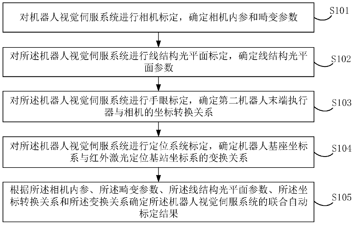
[0037] figure 1 It shows a schematic flowchart of a joint automatic calibration method for a robot visual servo system provided in this embodiment, including:

[0038] S101. Carry out camera calibration for the robot visual servo system, and determine camera internal parameters and distortion parameters.

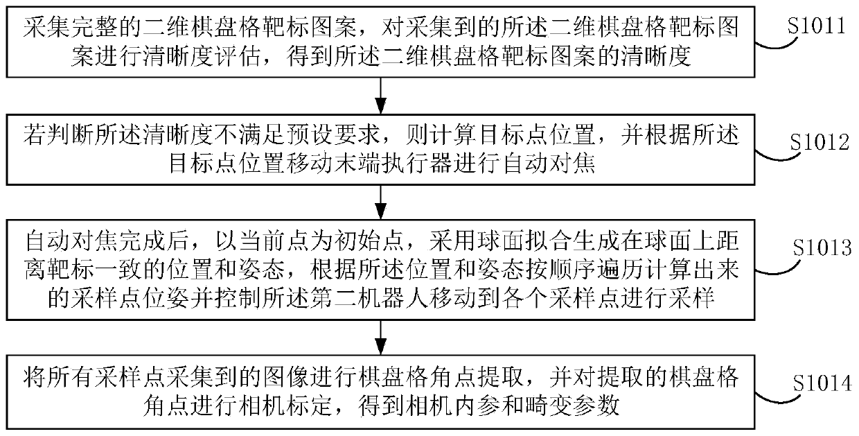
[0039] Specifically, the image acquisition requirements for camera calibration are the simplest, as long as the camera can capture a complete and clear target pattern, the acquisition conditions can be considered satisfied. Therefore, it is only necessary to fix the position of the calibration object in advance, calculate a series of positions and attitudes suitab...


PUM


Abstract

The embodiment of the invention discloses a joint automatic calibration method and device for a robot vision servo system, and the method comprises the steps: carrying out the camera calibration of the robot vision servo system, and determining the internal parameters and distortion parameters of a camera; performing line structured light plane calibration, and determining line structured light plane parameters; performing hand-eye calibration, and determining a coordinate conversion relation between a second robot end effector and a camera; performing positioning system calibration, and determining a transformation relation between a robot base coordinate system and an infrared laser positioning base station coordinate system; and determining a joint automatic calibration result of the robot vision servo system according to the camera internal parameters, the distortion parameters, the linear structure light plane parameters, the coordinate conversion relationship and the transformation relationship. Firstly, joint calibration of multiple sensing and positioning modes is realized, so that an industrial robot vision servo system is not limited to structured light vision sensing orbinocular vision sensing; secondly, the automation of the calibration process is realized, the manual operation is removed, and the working efficiency is improved.

Description

technical field [0001] The invention relates to the field of computer technology, in particular to a joint automatic calibration method and device for a robot visual servo system. Background technique [0002] The mechanical arm is the most widely used automatic mechanical device in the field of robotics. It is widely used in industrial manufacturing, medical treatment, entertainment services, military, semiconductor manufacturing and other fields. Although the common six-degree-of-freedom mechanical arm pose accuracy Now it can achieve a very high level, but to achieve high precision in actual use requires complex simulation and on-site teaching processes to achieve. At the same time, there are high requirements for the consistency of the workpiece, and it lacks the intelligence to correct deviations independently. [0003] In the 1960s, due to the development of robots and computer technology, people began to study robots with visual functions, aiming to collect and analyz...

Claims


Application Information

Patent Timeline
Patent Type & Authority Patents(China)
IPC IPC(8): G06T7/80
CPCG06T7/85
Inventor 郭颜京天刘昊
Owner 北京无远弗届科技有限公司
Learn More