Wet step-by-step removal of SO from flue gas 2 and no method

A flue gas and wet technology, applied in the integration of flue gas desulfurization and denitrification process, flue gas desulfurization or denitrification field, can solve the problems of absorbent loss, difficulty in decomposition, consumption of ammonia, etc., to achieve convenient control and operation, low operating costs Inexpensive, avoids failure effect

Active Publication Date: 2021-11-05
SHANGHAI UNIV
View PDF16 Cites 0 Cited by
  • Summary
  • Abstract
  • Description
  • Claims
  • Application Information

AI Technical Summary

Problems solved by technology

To solve this problem, the patent CN104084023A proposes to use ferrous chelating agent to complex absorb NO, and the absorption liquid is reduced to ammonia gas by metal iron to realize denitrification, and then ammonia gas is mixed with ammonia water in the desulfurization section, reacted with sulfur dioxide to obtain ammonium sulfite, and then oxidized Obtain ammonium sulfate to realize desulfurization. This process is also relatively simple, but it needs to consume ammonia and metal iron, which increases the cost of treatment.
[0012] In addition, if there is SO in the flue gas 2 , then the SO in the flue gas 2 It is easily absorbed by water and reacts with Fe(II)EDTA-NO to form Fe(II)EDTA(SO 3 2- )NO, the compound is extremely stable and difficult to decompose, resulting in the loss of absorbent

Method used


Image

  • Wet step-by-step removal of SO from flue gas  <sub>2</sub> and no method
  • Wet step-by-step removal of SO from flue gas  <sub>2</sub> and no method
  • Wet step-by-step removal of SO from flue gas  <sub>2</sub> and no method

Examples


Embodiment 1

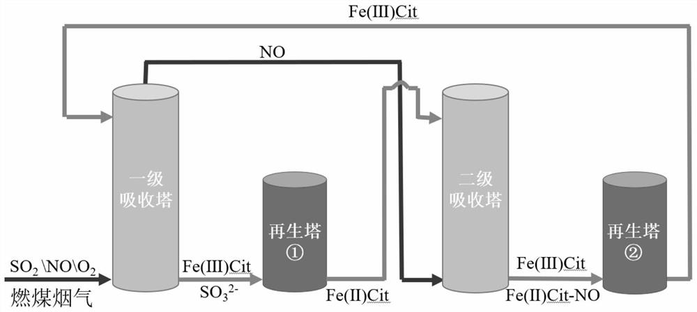
[0056] In this example, see figure 1 , set up an absorption and purification device, including a primary absorption tower, an absorption liquid regeneration tower ①, a secondary absorption tower, and an absorption liquid regeneration tower ②; 2 The gas with NO and NO is drawn out by the induced draft fan and enters the first-stage absorption tower from the bottom of the tower. The regenerated absorption liquid is a solution mainly containing Fe(III)Cit. The regenerated absorption liquid enters from the top of the tower after being pressurized by a water pump. Reverse flow, complete SO in the primary absorption tower 2 removal; the purified flue gas enters the bottom of the secondary absorption tower, and the primary absorption liquid flows into the absorption liquid regeneration tower ① for regeneration. After regeneration, a solution mainly containing Fe(II)Cit is obtained, and the regenerated secondary absorption The liquid is pumped into the top of the secondary absorption...

Embodiment 2

[0069] This embodiment is basically the same as Embodiment 1, especially in that:

[0070] In this embodiment, an absorption and purification device is set up, including a primary absorption tower, an absorption liquid regeneration tower ①, a secondary absorption tower, and an absorption liquid regeneration tower ②; 2 The gas with NO and NO is drawn out by the induced draft fan and enters the first-stage absorption tower from the bottom of the tower. The regenerated absorption liquid is a solution mainly containing Fe(III)Cit. The regenerated absorption liquid enters from the top of the tower after being pressurized by a water pump. Reverse flow, complete SO in the primary absorption tower 2 removal; the purified flue gas enters the bottom of the secondary absorption tower, and the primary absorption liquid flows into the absorption liquid regeneration tower ① for regeneration. After regeneration, a solution mainly containing Fe(II)Cit is obtained, and the regenerated secondar...

Embodiment 3

[0083] This embodiment is basically the same as the previous embodiment, and the special features are:

[0084] In this embodiment, an absorption and purification device is set up, including a primary absorption tower, an absorption liquid regeneration tower ①, a secondary absorption tower, and an absorption liquid regeneration tower ②; 2 The gas with NO and NO is drawn out by the induced draft fan and enters the primary absorption tower from the bottom of the tower. The regenerated absorption liquid is a solution mainly containing Fe(III)EDTA. The regenerated absorption liquid is pressurized by a water pump and then enters from the top of the tower. Reverse flow, complete SO in the primary absorption tower 2 removal; the purified flue gas enters the bottom of the secondary absorption tower, and the primary absorption liquid flows into the absorption liquid regeneration tower ① for regeneration. After regeneration, a solution mainly containing Fe(II)EDTA is obtained, and the r...


PUM


Abstract

The invention discloses a wet method for step-by-step removal of SO in flue gas 2 and NO method, the flue gas to be purified is continuously passed into the primary absorption tower and the secondary absorption tower; in the primary absorption tower, the SO in the flue gas 2 After contacting with the primary absorption liquid, it is absorbed and removed. In the secondary absorption tower, the NO in the flue gas is absorbed and removed after contacting the secondary absorption liquid, and the purified gas is discharged; the primary absorption liquid absorbs SO 2 After entering the regeneration tower ①, under the catalysis of the biochar catalyst, the iron-organic complex is transformed; after the secondary absorption liquid complexes and absorbs NO, it enters the regeneration tower ②, where the iron-organic complex is transformed, and the regenerated absorption liquid It then enters the first-stage absorption tower and is recycled in the system. The method of the present invention realizes SO in flue gas 2 The step-by-step and efficient green removal of NO and NO, the absorbent used can be recycled, and the removal process does not need to add other desulfurization and denitrification chemicals.

Description

technical field [0001] The invention relates to a flue gas desulfurization or denitrification method, in particular to a flue gas desulfurization and denitrification process integration method, which is applied in the technical fields of waste gas purification and environmental protection engineering. Background technique [0002] Sulfur oxides (SO X ) and nitrogen oxides (NO X ) is the main pollutant causing air pollution. The man-made emissions of these pollutants mainly come from the combustion process of fossil resources such as coal and fuel oil and the chemical production process. They have the characteristics of large smoke emissions and concentrated pollutant emissions, which can easily cause regional air pollution problems. Sulfur oxides (SOx) emitted from combustion flue gas X ) is mainly sulfur dioxide (SO 2 ), nitrogen oxides (NO X ) is mainly nitric oxide (NO), accounting for more than 90%. Therefore, to SO 2 The removal of NO and NO is the focus of combu...

Claims


Application Information

Patent Timeline
Patent Type & Authority Patents(China)
IPC IPC(8): B01D53/14
CPCB01D53/1425B01D53/1456B01D53/1481B01D2258/0283
Inventor 於柯言胡甜刘扬刘畅刘强
Owner SHANGHAI UNIV
Why Eureka
Try Eureka