
Sensorless brushless DC motor commutation position correction system and method

A brushed DC motor and sensor technology, applied in the control system, electronic commutation motor control, electrical components, etc., can solve the problems of poor motor control and operation performance, inaccurate commutation position detection, commutation position deviation, etc. Achieve fast and accurate correction, improve control and operation performance, and achieve the effect of less detection

Active Publication Date: 2019-08-09
YANCHENG INST OF TECH
View PDF3 Cites 7 Cited by
  • Summary
  • Abstract
  • Description
  • Claims
  • Application Information

AI Technical Summary

Problems solved by technology

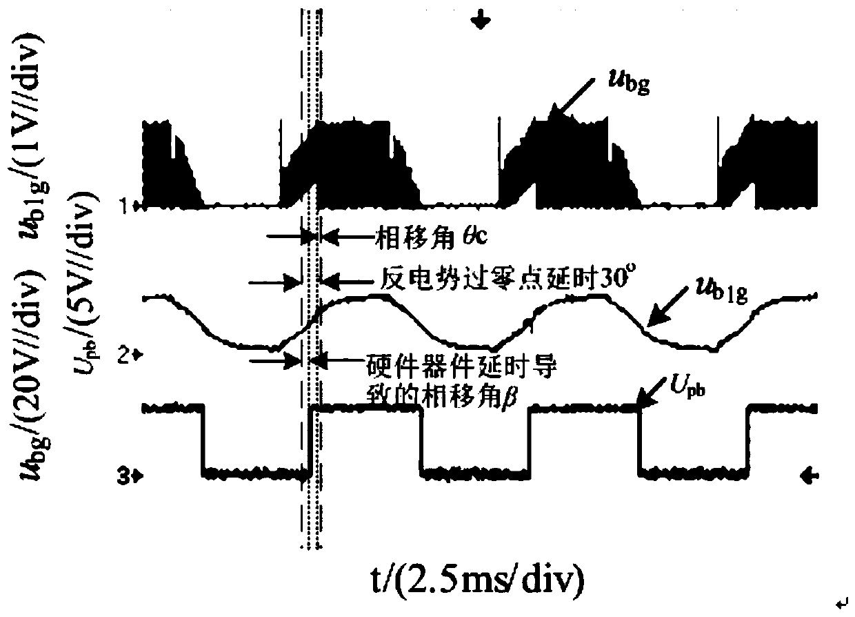
The most commonly used position detection method for sensorless brushless DC motors is the back-emf zero-crossing method, which determines the commutation position of the rotor according to the back-emf zero-crossing point, but this method will be affected by the phase caused by the filter circuit in the back-emf zero-crossing detection circuit The influence of phase shift caused by factors such as offset, detection circuit device delay, and control chip software calculation delay makes the commutation position detection inaccurate, resulting in deviation of the commutation position, and deterioration of motor control and operation performance. In severe cases, even May cause the motor to lose step

Method used


Image

  • Sensorless brushless DC motor commutation position correction system and method
  • Sensorless brushless DC motor commutation position correction system and method
  • Sensorless brushless DC motor commutation position correction system and method

Examples


Embodiment Construction

[0048] In order to make the technical means, creative features, goals and effects achieved by the present invention easy to understand, the present invention will be further described below in conjunction with specific embodiments.

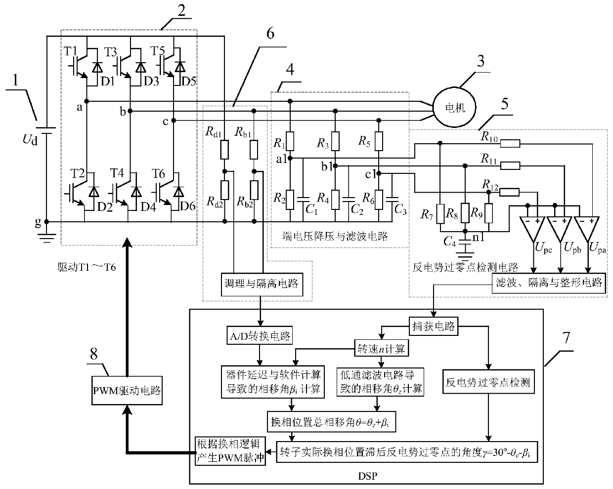
[0049] attached figure 1 It is the sensorless brushless DC motor commutation position correction system of the present invention, including a DC power supply 1, a three-phase full-bridge inverter 2, a brushless DC motor 3, a terminal voltage step-down and filter circuit 4, and a back EMF zero-crossing point Detection circuit 5, DC bus and b-phase terminal voltage detection circuit 6, digital signal processor 7, PWM signal drive circuit 8;

[0050] The three-phase full-bridge inverter 2 inverts the DC power provided by the DC power supply 1 into AC power to supply power to the three-phase windings of the brushless DC motor 3, and the terminal voltage of the three-phase windings of the brushless DC motor 3 passes through the terminal voltage step-do...


PUM


Abstract

The invention discloses a sensorless brushless DC motor commutation position correction system and method. The system comprises a DC power supply, a three-phase full-bridge inverter, a brushless DC motor, a terminal voltage step-down and filtering circuit, a counter potential zero crossing detection circuit, a DC bus and a b-phase terminal voltage detection circuit, a digital signal processor anda PWM signal driving circuit. The counter potential zero crossing offset caused by filtering and the commutation position offset caused by the hardware circuit device delay and the software calculation delay can be simultaneously compensated by detecting the DC bus voltage and the terminal voltage. Compared with the existing sensorless brushless DC motor commutation position correction system, therequired detection amount is low, the calculation workload is low, the rotor commutation position offset can be quickly and accurately corrected, the accurate rotor commutation position can be obtained and the control and operation performance of the brushless DC motor can be enhanced. The sensorless brushless DC motor commutation position correction system has high universality and is suitable for the sensorless brushless DC motor control system using multiple control strategies.

Description

technical field [0001] The invention relates to the technical field of motor control, in particular to a commutation position correction system and method for a brushless DC motor without a position sensor. [0002] Background technique: [0003] Brushless DC motors are widely used in household appliances, instrumentation, chemical textiles, office automation equipment, and medical equipment because of their advantages such as simple structure, stable operation, high efficiency, and convenient maintenance. The brushless DC motor needs to provide the commutation information of the three-phase winding according to the rotor position, but the installation of the position sensor not only increases the volume and cost of the motor, but also increases the number of signal lines, which will reduce the reliability of the motor operation. In order to make the motor run stably in a complicated working environment, the position sensorless control technology of brushless DC motor has bee...

Claims


Application Information

Patent Timeline
IPC IPC(8): H02P6/182
CPCH02P6/182
Inventor 张兰红仓竹荣杨婷婷姚冲何坚强朱文秀
Owner YANCHENG INST OF TECH
Learn More