
Current overload protection method

A current overload and current technology, applied in the circuit field, can solve problems such as double-chip bounce fatigue, prolong the service life of the protector, and fail to work normally, and achieve the effects of sensitive sensitivity, simple and convenient operation, and enhanced safety

Active Publication Date: 2021-09-03
深圳市英唐智能控制股份有限公司
View PDF6 Cites 0 Cited by
  • Summary
  • Abstract
  • Description
  • Claims
  • Application Information

AI Technical Summary

Problems solved by technology

[0002] With the development of industrial technology, power supplies and various electrical appliances have penetrated into various fields of people's daily life and work. With the increasing use of various electrical appliances, the safety problems of using electrical appliances have become increasingly prominent. Generally, the electrical equipment will be connected in series with the overload protector. The overload protector will cause the bimetal sheet to be heated and deformed by the current overload and separate the dynamic and static contacts, so as to achieve the purpose of protecting the electrical equipment. However, in some loads that change frequently The equipment will cause the overload protector to cut off the current frequently, and the elastic recovery of the bimetal is limited. After exceeding the elastic recovery limit, it is likely to cause double-plate bounce fatigue, or contact welding due to abnormal current 1. The adhesion causes the overload protector to fail to work normally. These reasons lead to the failure of the bimetal sheet to be heated and deformed normally, causing the overload protector to fail. For this reason, the inventor designed a protector that adopts a thermal expansion automatic circuit breaker, which can automatically sense the circuit Whether the current is overloaded determines whether to cut off the power supply, the circuit reset only needs the user to manually press the recovery lever, which greatly increases the safety performance, and at the same time uses the heat expansion and contraction fluid as the medium, which greatly prolongs the service life of the protector

Method used


Image

  • Current overload protection method
  • Current overload protection method
  • Current overload protection method

Examples


Embodiment Construction

[0073] A current overload protection method, the steps of which are:

[0074] (1) Overload stage;

[0075] S1: Whether the current of the induction circuit of the protector body 100 is overloaded;

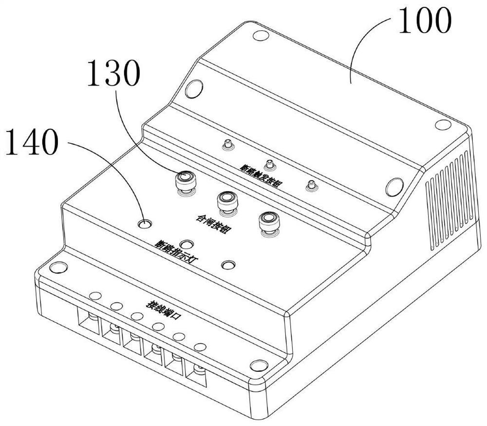
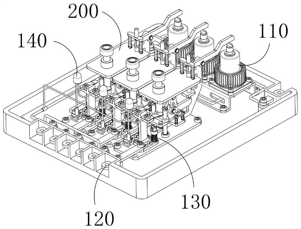
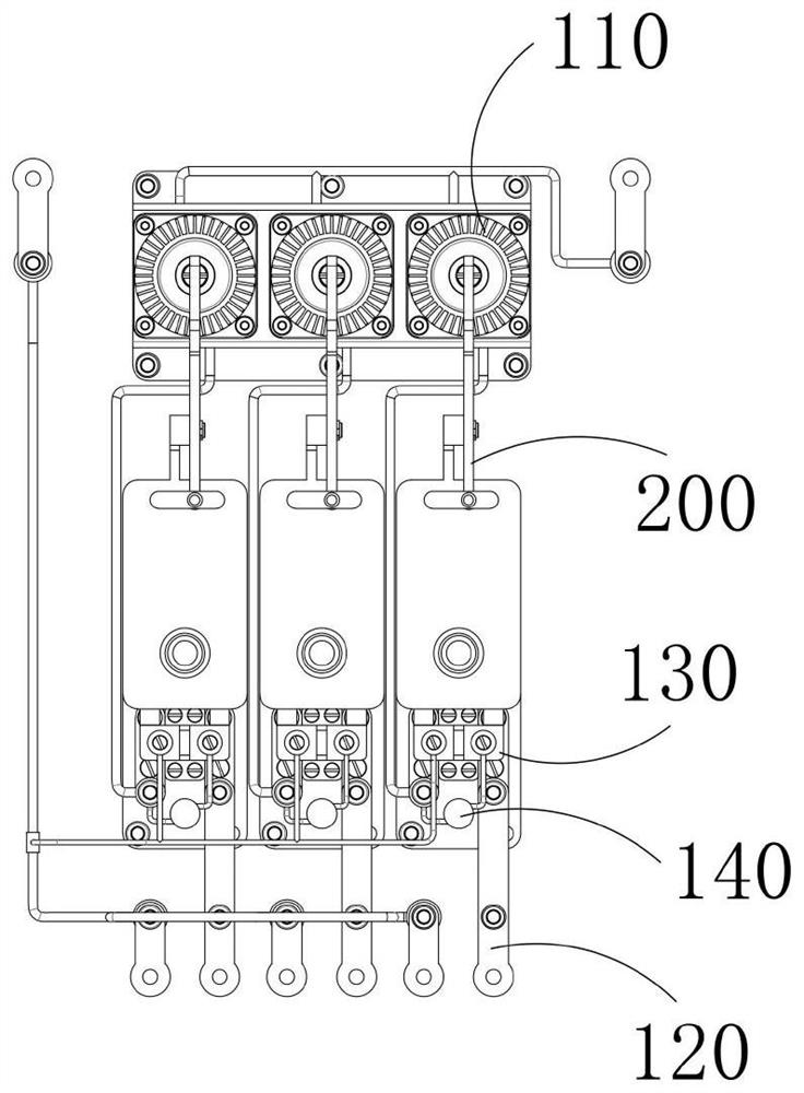
[0076] The protector body 100 includes a horizontally placed installation case, and a circuit wiring mechanism 120 and a protection mechanism are installed in the installation casing. The circuit connection mechanism 120 is used for circuit wiring between power supplies, electrical equipment, and protection mechanisms. The protection mechanism includes an overload sensing member 110 and a circuit connecting member 130. The overload sensing member 110 is used to automatically sense whether the circuit current is overloaded. The circuit connecting member 130 is used to control the circuit flow between the power supply current and the electrical equipment, and the circuit connecting member 130 It can be divided into the closed state that enables the current to be smoothly transmitted...


PUM


Abstract

The invention discloses a current overload protection method, the steps of which are: when the current is overloaded, the overload sensing component generates heat and thermally expands the thermal expansion and contraction fluid, and the overload sensing component switches to the overload state; the top column inside the overload sensing component contacts the trigger mechanism and The trigger mechanism is triggered, and the limiting mechanism is switched from the limiting state to the canceling state, and at the same time, the circuit connection member is switched to the disconnected state under the elastic force of the separation spring inside itself, and the circuit is disconnected; the user eliminates the overload fault and stops for a period of time Finally, the thermal expansion and contraction fluid heats up and returns to its original state, and the overload sensing component switches to the normal state; the user presses the circuit connecting component to switch the circuit connecting component to the closed state, the limiting mechanism switches to the restricting state, and the circuit returns to normal ; The trigger mechanism can be triggered by pressing the power-off lever by the user, so that the circuit is manually disconnected by the user.

Description

technical field [0001] The invention relates to the field of circuits, in particular to a circuit current overload protection method. Background technique [0002] With the development of industrial technology, power supplies and various electrical appliances have penetrated into various fields of people's daily life and work. With the increasing use of various electrical appliances, the safety problems of using electrical appliances have become increasingly prominent. Generally, the electrical equipment will be connected in series with the overload protector. The overload protector will cause the bimetal sheet to be heated and deformed by the current overload and separate the dynamic and static contacts, so as to achieve the purpose of protecting the electrical equipment. However, in some loads that change frequently The equipment will cause the overload protector to cut off the current frequently, and the elastic recovery of the bimetal is limited. After exceeding the elas...

Claims


Application Information

Patent Timeline
Patent Type & Authority Patents(China)
IPC IPC(8): H02H3/08H02H3/04H01H73/30H01H73/20H01H73/14
CPCH01H73/14H01H73/20H01H73/30H02H3/04H02H3/085
Inventor 梁根如
Owner 深圳市英唐智能控制股份有限公司
Learn More