
A transmission system for aerodynamics

A transmission system and aviation power technology, applied to transmission parts, automatic clutches, clutches, etc., can solve problems such as limited transmission torque, wear, and large shaft tension, and achieve good economical results

Active Publication Date: 2022-03-29
CHONGQING ZONGSHEN AERO ENGINE MFG CO LTD
View PDF10 Cites 0 Cited by
  • Summary
  • Abstract
  • Description
  • Claims
  • Application Information

AI Technical Summary

Problems solved by technology

[0004] In the above-mentioned patents, the transmission torque is limited, and the claws are subject to a large impact load, which makes the contact force of the claws too large, resulting in wear, and also makes the shaft tension too large and easily damaged.

Method used


Image

  • A transmission system for aerodynamics
  • A transmission system for aerodynamics
  • A transmission system for aerodynamics

Examples


Embodiment

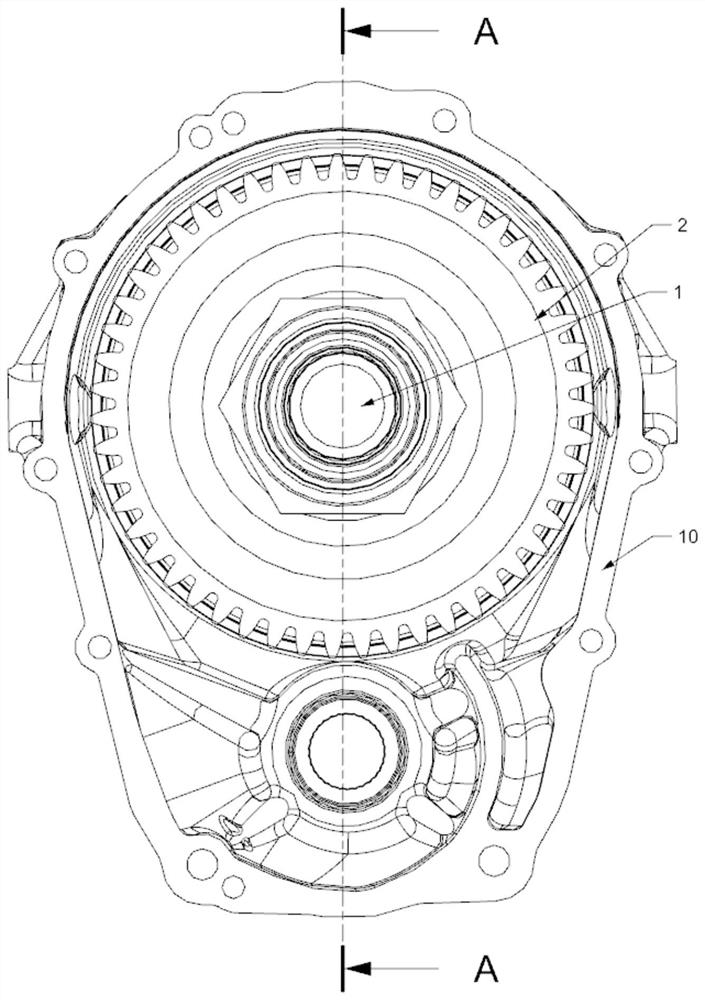
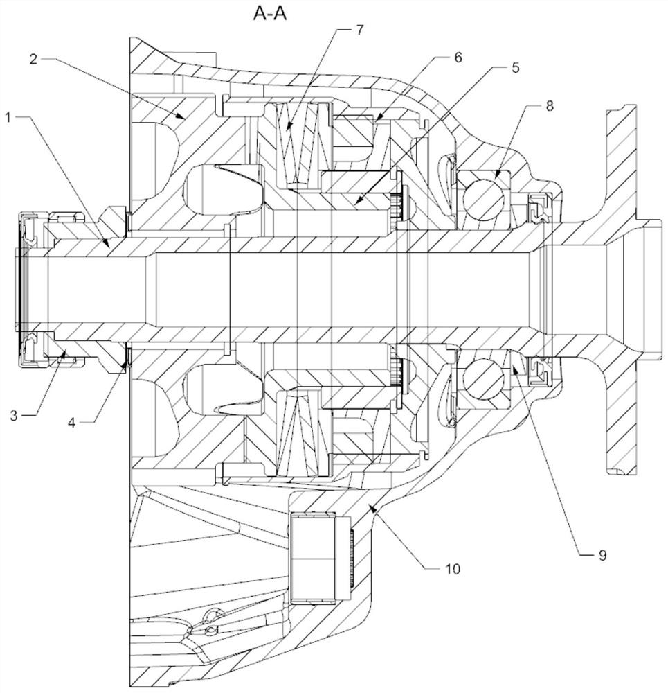
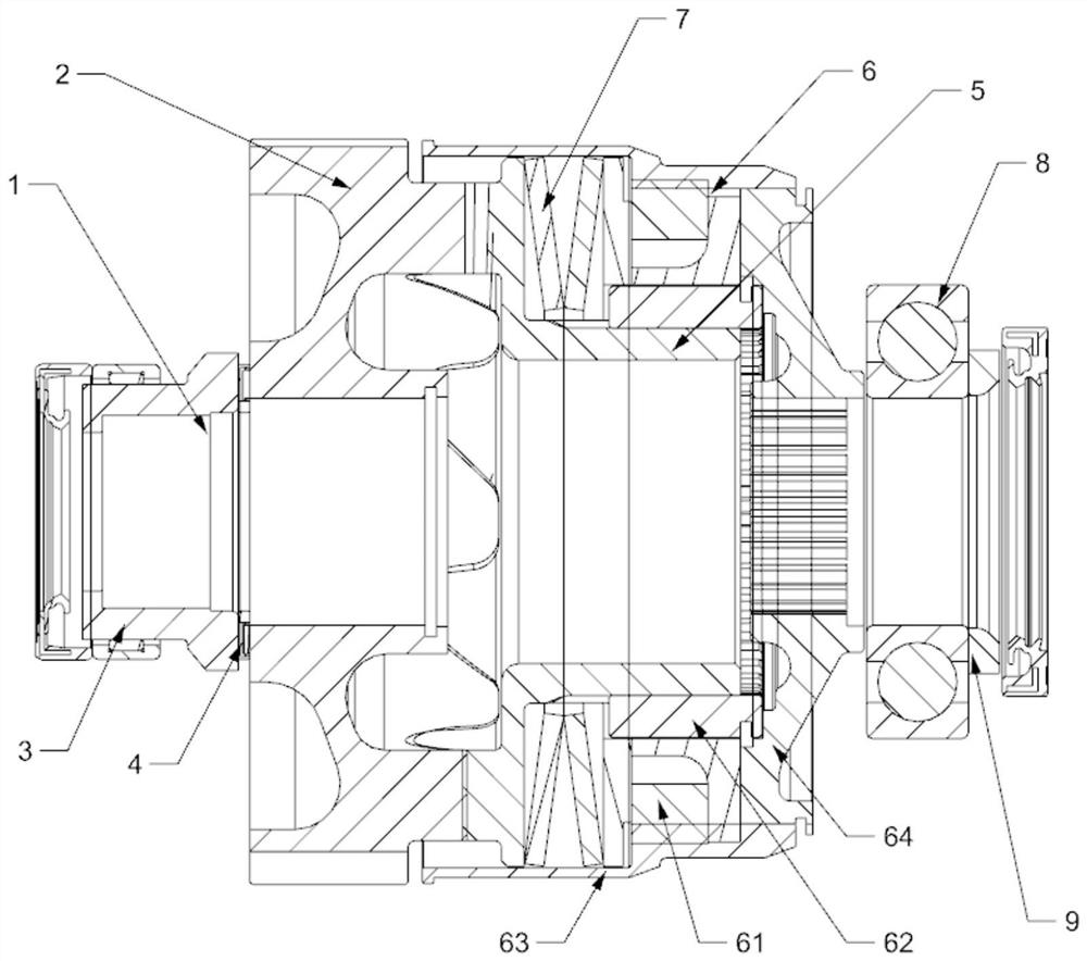
[0031] Example: such as Figure 1-6 As shown, this embodiment provides a transmission system for aerodynamics, for example, it can be used on aircraft such as drones and helicopters. Including a transmission shaft 1, the input end of the transmission shaft is vacantly sleeved with a driven gear 2 and one end of the driven gear is axially limited, the other end of the transmission shaft is used to connect a rotating member, and the rotating member Usually a propeller.

[0032] In this embodiment, the end of the driven gear away from the propeller is limited by the bushing 3 , and a needle bearing 4 is arranged between the end face of the bushing and the end face of the driven gear. The driven gear is meshed with the driving gear in the transmission case, and the driving gear is connected to the power output shaft of the aeroengine, and the engine transmits power to the driving gear, and then to the driven gear.

[0033] The other end of the driven gear is in transmission conn...


PUM


Abstract

The invention discloses a transmission system for aerodynamic power, comprising a transmission shaft, an input end of the transmission shaft is hollowly sleeved with a driven gear, one end of the driven gear is axially limited, and the other end of the transmission shaft is axially limited. One end is used to connect the rotating member, and it is characterized in that: the other end of the driven gear is drivingly connected with the stopper hub, the stopper hub is drivingly connected with the overload clutch, and the overload clutch is drivingly connected with the transmission shaft, so A disc spring member is sandwiched between one end of the overload clutch and the stop hub, the other end of the overload clutch is axially limited, and there is a limiting distance between the overload clutch and the brake hub; The force value of the overload clutch varies with the pressure; the end face of the driven gear facing the stop hub is provided with a pawl A, and one end of the stop hub is provided with a pawl B matched with the convex pawl A , the stop hub and the driven gear are driven through the cooperation of the claws.

Description

technical field [0001] The invention relates to a power transmission system, especially a transmission system for aviation power. Background technique [0002] Aviation power, including helicopters, drones, or power systems of various aircraft. In its engine transmission mechanism, the power is transmitted from the main transmission shaft (crankshaft) to the driving gear, and then the driving gear drives the driven gear to rotate, and finally the transmission shaft transmits its rotation to the rotating member (propeller shaft, driving method Lan, etc.). On the existing driven teeth, a clutch is often installed on the rotating member, and the clutch is connected with the rotating member through a spline. When the rotating member is subjected to an external force that exceeds the ability of the member during the movement and transmission of power, the clutch and the rotating member will temporarily separate from the direction of rotation, that is, the clutch and the rotatin...

Claims


Application Information

Patent Timeline
Patent Type & Authority Patents(China)
IPC IPC(8): F16H57/023F16H57/021F16D43/21
CPCF16H57/023F16H57/021F16D43/21F16H35/10Y02T50/40F16H2057/02082F16H57/043F16H57/0473F16D7/044F16D43/2022B64D35/00
Inventor 周丹熊银超皮礼平唐中
Owner CHONGQING ZONGSHEN AERO ENGINE MFG CO LTD
Learn More