
current overload protector

A technology of current overload and protector, which is applied in the field of circuits, can solve the problems of increasing safety performance, safety hazards and dangers of quick reset of the protector, and achieves the effects of simple and convenient operation, enhanced safety, and sensitive sensitivity

Active Publication Date: 2021-03-09
神州技测(上海)电子科技有限公司
View PDF9 Cites 0 Cited by
  • Summary
  • Abstract
  • Description
  • Claims
  • Application Information

AI Technical Summary

Problems solved by technology

[0002] The 21st century is an era of informatization. The rapid development of informatization has made people more and more dependent on electronic equipment and products, and these electronic equipment and products are inseparable from power supplies. The safety of power supplies has become the focus of attention. , in order to ensure the safety of electricity use, people set up a current overload protector in electrical appliances. The traditional current overload protector will cause the bimetal to heat and deform through current overload, and separate the dynamic and static contacts to achieve the purpose of cutting off the power supply circuit. However, the bimetal sheet of this kind of current overload protector usually recovers its deformation within a few seconds and resets the circuit. If it is necessary to detect and repair the electrical appliance, the power supply must be cut off first. Cutting off the power supply for maintenance, the rapid reset of the protector will bring a greater safety hazard, or due to the negligence of the maintenance personnel, it will be very dangerous to perform maintenance and testing of electrical appliances without cutting off the power supply. For this reason, the present invention I designed a protector that adopts the thermal expansion automatic circuit breaking method, which can automatically sense whether the circuit current is overloaded and decide whether to cut off the power supply. At the same time, the circuit reset only needs the user to manually press the recovery lever, which greatly increases the safety performance.

Method used


Image

  • current overload protector
  • current overload protector
  • current overload protector

Examples


Embodiment Construction

[0064] The present invention adopts the automatic trigger circuit breaker to cut off the internal current flow of the protector body under the overload state. The purpose of protection, in which the body of the protector uses thermal expansion and contraction fluid and the sensing resistor to sense whether the current of the circuit is overloaded, the sensitivity is more sensitive, and the overload alarm mechanism can enable the user to know in real time whether the circuit is overloaded, and whether the circuit has recovered after overloading In addition, the user eliminates the overload fault and presses the recovery lever of the circuit connecting member to restore the protector body to its original state, that is, the circuit returns to normal, and the user does not need to disassemble and restore the protector body, and the operation is more convenient. Simple, convenient and greatly enhanced security.

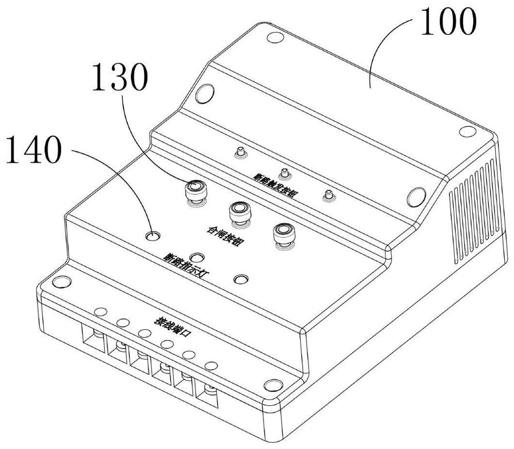
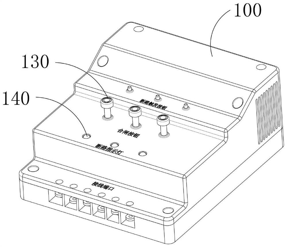
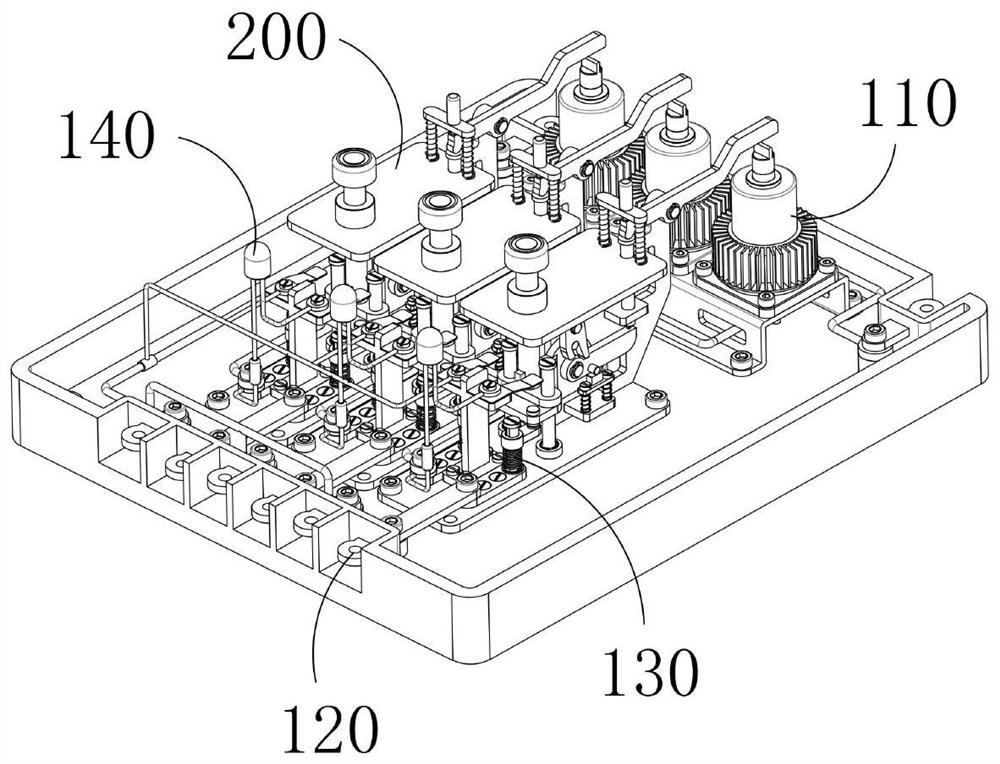
[0065] The current overload protector includes a protector body 100 ...


PUM


Abstract

The invention provides a current overload protector. The current overload protector comprises a protector body, an automatic triggering and disconnecting device; the protector body comprises a mounting housing, wherein a circuit wiring mechanism and a protection mechanism are mounted in the mounting housing; the circuit wiring mechanism is used for circuit wiring between a power supply, electricalequipment and the protection mechanism; the protection mechanism comprises an overload sensing component used for automatically sensing whether the circuit current is overloaded or not, and a circuitconnecting component used for controlling the circuit circulation between the power supply current and the electrical equipment; the automatic triggering and disconnecting device comprises a limitingmechanism, a triggering mechanism and a resetting mechanism, wherein the limiting mechanism is used for limiting the movement of a conductive plate far away from a conductive sheet b under the actionof the elastic force of a separation spring; the triggering mechanism is used for being triggered by an overload sensing component and enabling the limiting mechanism to withdraw the limitation of the conducting plate; and the resetting mechanism is used for assisting the automatic triggering device to restore to the original shape.

Description

technical field [0001] The invention relates to the field of circuits, in particular to a current overload protector. Background technique [0002] The 21st century is an era of informatization. The rapid development of informatization has made people more and more dependent on electronic equipment and products, and these electronic equipment and products are inseparable from power supplies. The safety of power supplies has become the focus of attention. , in order to ensure the safety of electricity use, people set up a current overload protector in electrical appliances. The traditional current overload protector will cause the bimetal to heat and deform through current overload, and separate the dynamic and static contacts to achieve the purpose of cutting off the power supply circuit. However, the bimetal sheet of this kind of current overload protector usually recovers its deformation within a few seconds and resets the circuit. If it is necessary to detect and repair t...

Claims


Application Information

Patent Timeline
Patent Type & Authority Patents(China)
IPC IPC(8): H01H81/02H01H71/14
CPCH01H71/14H01H81/02H01H2071/147
Inventor 梁根如
Owner 神州技测(上海)电子科技有限公司
Learn More