Cathode wire machining mechanism

A processing mechanism and cathode wire technology, applied in electrode structure, electrostatic effect separation, solid separation and other directions, can solve the problems of cumbersome production methods, low production efficiency, time-consuming and labor-intensive, etc., to achieve stable driving mechanism structure, improve processing efficiency, reduce The effect of production costs

Active Publication Date: 2019-07-30
JIANGSU YONGJI CHEM EQUIP
View PDF11 Cites 1 Cited by
  • Summary
  • Abstract
  • Description
  • Claims
  • Application Information

AI Technical Summary

Problems solved by technology

[0003] Cathode wires are also called prickly wires or corona wires, which can be installed in various horizontal or vertical electrostatic precipitators, and have good volt-ampere characteristics. The specific structure of the thorn-shaped cathode line includes a rod body and discharge teeth arranged in sequence along the length of the rod body. The discharge of the discharge teeth makes the dust or fog droplets electrified, and there are no discharge teeth at both ends of the cathode line, which is convenient for the cathode The wire is connected to the frame of the cathode system. When processing this type of cathode wire, place the semi-finished cathode wire with wings in the mold, place the mold on the worktable of the press, and stamp the wings into discharge teeth by stamping. Then remove the discharge teeth at both ends of the rod body manually or by other equipment. This production method has a tooth forming process of stamping the discharge teeth and a tooth removal process of removing the discharge teeth at both ends of the rod body. The production method is cumbersome and requires It is time-consuming and labor-intensive to process the discharge teeth at both ends after removing the cathode wire of the punched discharge teeth from the press machine, and the production efficiency is low

Method used


Image

  • Cathode wire machining mechanism
  • Cathode wire machining mechanism
  • Cathode wire machining mechanism

Examples


specific Embodiment

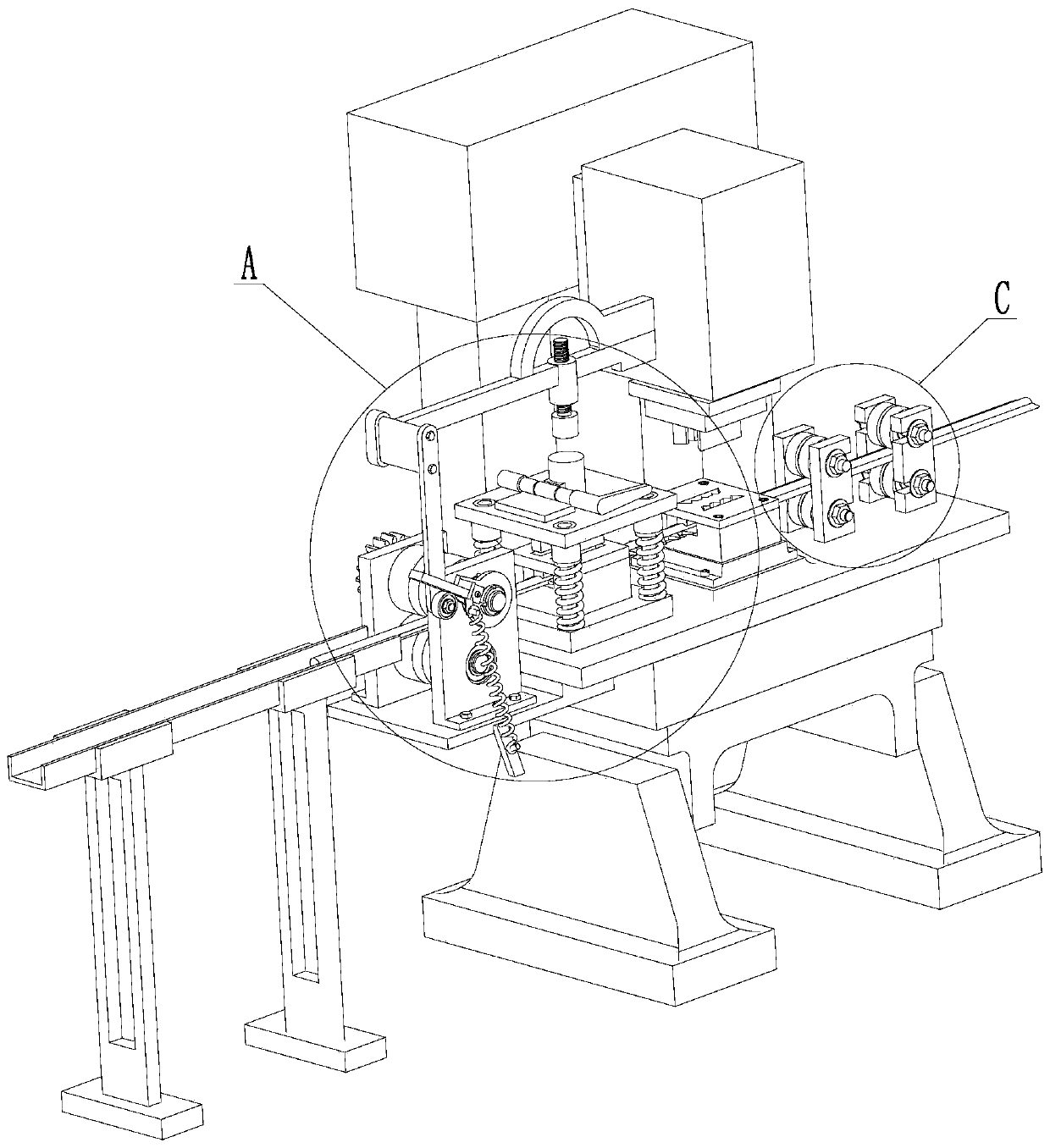
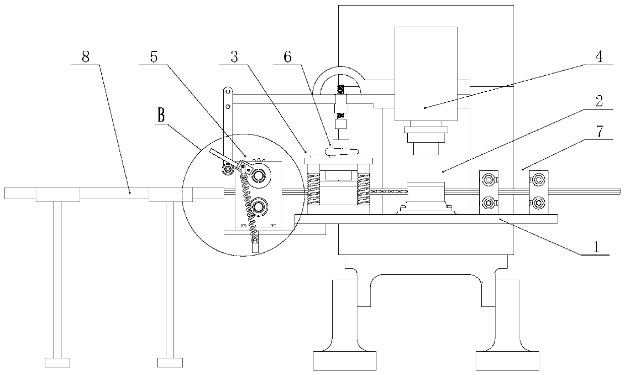
[0037] Such as figure 1 , 2 As shown in 4, a cathode wire processing mechanism includes an electric discharge tooth machining unit 2 and an electric discharge tooth removal unit 3 installed on a press workbench 1. The electric discharge tooth machining unit is used to process the electric discharge teeth of a semi-finished cathode wire, and the electric discharge tooth removal The unit is used to remove the discharge teeth at both ends of the cathode wire to facilitate the installation of the cathode wire. The electrical discharge gear processing unit and the electrical discharge gear removal unit are arranged at intervals along the feeding direction, so that the semi-finished cathode wire can be removed by the electrical discharge gear processing unit and the electrical discharge teeth in turn Unit; the electric discharge tooth machining unit includes a toothed abrasive 201, the toothed mold includes a toothed lower mold installed on the worktable and a toothed upper mold instal...


PUM


Abstract

The invention discloses a cathode wire machining mechanism. The cathode wire machining mechanism comprises a discharge tooth machining unit and a discharge tooth removal unit, wherein the discharge tooth machining unit is arranged on a workbench of a press machine, the discharge tooth machining unit is used for machining discharge teeth, and the discharge tooth removal unit is used for removing the discharge teeth; the discharge tooth machining unit comprises a tooth forming grinding tool; and the discharging tooth removal unit comprises a tooth removing die, a movable plate, a sliding column,an elastic piece and a linkage mechanism, the sliding column is arranged on the workbench, the sliding column is connected with the movable plate in a sliding manner, the elastic piece is arranged between the movable plate and the workbench, the linkage mechanism comprises a cross rod and a stud, the cross rod is connected with a press slide block, and the stud is arranged above the movable plateand connected with a threaded hole of the cross rod. The discharge tooth machining unit and the discharge tooth removal unit are integrated to the workbench of the press machine, so that the functions of synchronously machining the discharge teeth in the middle of a cathode wire and removing the discharge teeth at the end of the cathode wire are realized, the machining efficiency is greatly improved, the field, equipment and labor use are reduced, and the production cost is reduced.

Description

Technical field [0001] The invention relates to the technical field of cathode wire processing, in particular to a mechanism for processing the middle external teeth of the cathode wire and removing the external teeth at both ends. Background technique [0002] Electrostatic precipitator is an efficient industrial dust removal device used to treat dust in industrial waste gas. It is widely used in petroleum, chemical industry, electric power and other industrial fields. The electrostatic precipitator includes a cathode system and an anode system. The cathode system discharges dust, The fog droplets are charged, and then the charged dust and fog droplets are absorbed by the anode system, and finally the dust and fog droplets are peeled off by vibrating, so as to achieve the purification of exhaust gas. The cathode wire is an important component of the cathode system. [0003] Cathode wire is also called barbed wire or corona wire. It can be installed in various horizontal or vertica...

Claims


Application Information

Patent Timeline
IPC IPC(8): B21D22/02B21D35/00B03C3/43
CPCB21D22/02B21D35/002B03C3/43B03C2201/10B03C2201/04Y02P10/20
Inventor 贾永季吴建军张万勇许长桥罗勇
Owner JIANGSU YONGJI CHEM EQUIP
Why Eureka
Try Eureka