Eureka AIR delivers breakthrough ideas for toughest innovation challenges, trusted by R&D personnel around the world.

Power supply device and laser apparatus

A technology of power supply device and charging power supply, which is applied to lasers, laser parts, excitation methods/devices, etc., can solve the problems of DC voltage rise, departure from the allowable range, etc., and achieve the effect of increasing the operating frequency

Pending Publication Date: 2019-07-23
SUMITOMO HEAVY IND LTD
View PDF10 Cites 1 Cited by
  • Summary
  • Abstract
  • Description
  • Claims
  • Application Information

AI Technical Summary

Problems solved by technology

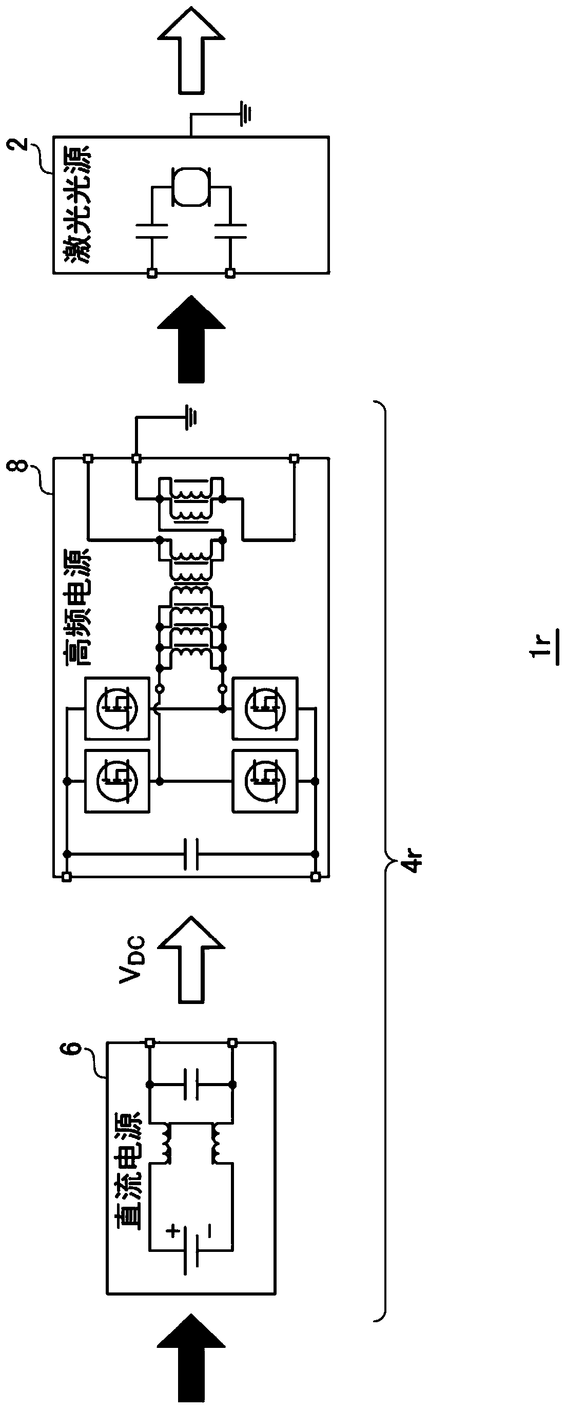
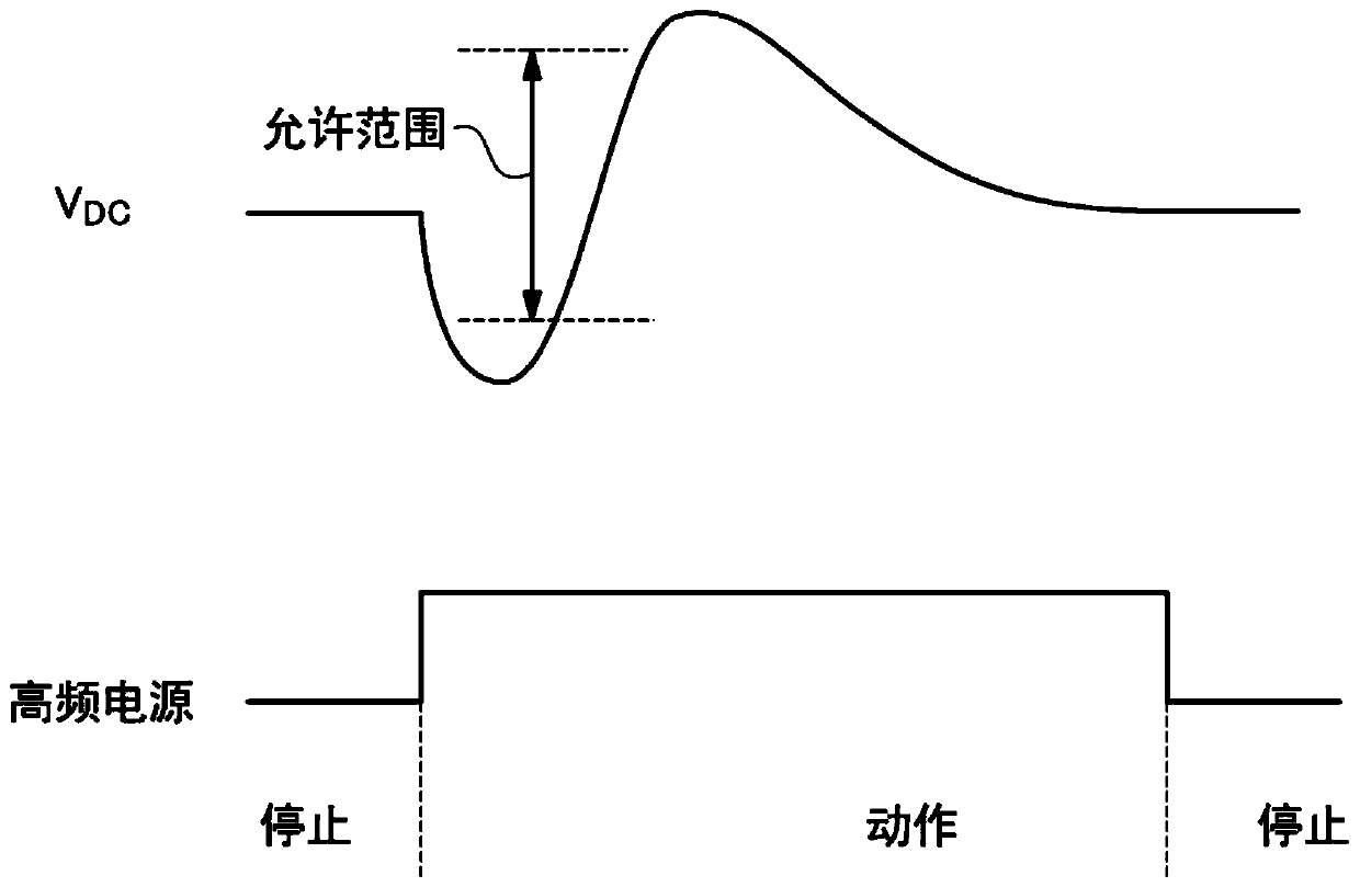
When the high-frequency power supply 8 is transferred from the stop period to the operation period, there will be a feedback response delay in the DC power supply 6, which may cause the DC voltage V DC drop out of allowable range
When the high-frequency power supply 8 is transferred from the operation period to the stop period, the feedback delay may cause the DC voltage V DC rise out of permissible range

Method used


Image

  • Power supply device and laser apparatus
  • Power supply device and laser apparatus
  • Power supply device and laser apparatus

Examples


Embodiment Construction

[0032] Hereinafter, preferred embodiments of the present invention will be described with reference to the drawings. In each drawing, the same or equivalent constituent elements, members, and processes are assigned the same symbols, and redundant descriptions are appropriately omitted. Furthermore, the embodiments are not intended to limit the invention but are examples, and all the features described in the embodiments or combinations thereof are not necessarily essential to the invention.

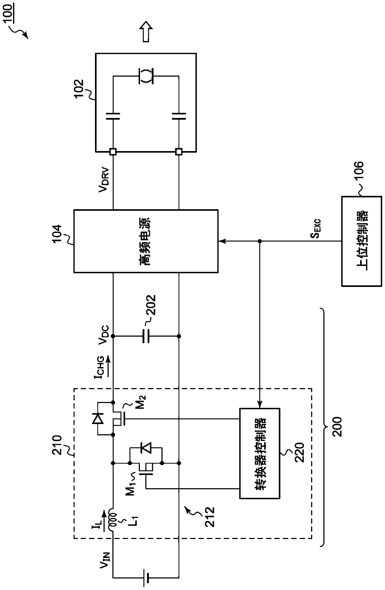
[0033] image 3 It is a block diagram of a laser device 100 including a power supply device 200 according to the embodiment. The laser device 100 includes a laser light source 102 , a high-frequency power source 104 , a host controller 106 , and a power source device 200 . The laser light source 102 is, for example, CO 2 laser. The host controller 106 generates an excitation signal S that instructs the laser light source 102 to activate (emit light) or stop EXC .

[0034] The input ...


PUM


Abstract

The invention provides a power supply device capable of improving the operation frequency of a load performing intermittent operation. A power supply device (200) is provided with a capacitor bank (202) and a charging power supply (210). A high-frequency power supply (104), which is a load that operates intermittently, is connected to the capacitor bank (202). The charging power supply (210) includes a switching converter (212) and charges the capacitor bank (202). A charging power supply (210) performs primary charging for turning on a low-side transistor (M1) of a switching converter (212) once, starting from the operation of a high-frequency power supply (104) being a load.

Description

[0001] This application claims priority based on Japanese Patent Application No. 2018-005849 filed on January 17, 2018. The entire contents of this Japanese application are incorporated herein by reference. technical field [0002] The invention relates to a power supply device and a laser device. Background technique [0003] As industrial processing tools, laser processing devices are widely used. figure 1 It is a block diagram of the laser processing apparatus 1r. Laser processing device 1r equipped with CO 2 A laser light source 2 such as a laser, and a laser drive device 4r that supplies alternating current to the laser light source 2 to drive it. The laser drive device 4 r includes a DC power supply 6 and a high-frequency power supply 8 . The DC power supply 6 is a constant-voltage power supply whose output (that is, the DC voltage V DC ) stabilized at the target value. The high frequency power supply 8 accepts the DC voltage V DC , and convert it into an altern...

Claims


Application Information

Patent Timeline
IPC IPC(8): H03K3/57H03K3/011H01S3/0975
CPCH03K3/57H03K3/011H01S3/09702H01S3/0975Y02B70/10H02M3/156H01S3/09
Inventor 原章文石挺
Owner SUMITOMO HEAVY IND LTD
Why Eureka
Eureka Blog
Learn More