
Chemical mechanical planarization device

A chemical-mechanical and flattening technology, applied in metal processing equipment, grinding machine tools, grinding devices, etc., can solve the problems such as the inability of the wafer to be cleaned in the first time, which is not conducive to industrialized mass production, and increases the waiting time of wafer queuing. , to achieve the effect of mechanization and automation of production, realization of refined production, and elimination of wafer transfer and queuing time

Inactive Publication Date: 2019-07-23
HANGZHOU ZHONGGUI ELECTRONICS TECH CO LTD
View PDF6 Cites 5 Cited by
  • Summary
  • Abstract
  • Description
  • Claims
  • Application Information

AI Technical Summary

Problems solved by technology

[0002] At present, in the existing semiconductor production technology field, the polishing unit and the acid tank cleaning process equipment are separated, and the polished wafers in a wet state need to be transported to the acid tank cleaning process equipment through the transmission unit, which has long strokes and high efficiency. The shortcomings of low cost and complex process constitute an obstacle to the batch planarization of wafers
At the same time, the existing separate equipment is not conducive to the intelligent transformation of the production process, and it is impossible to coordinate the cooperation between various equipment in the processing process; the waiting time of wafers is increased in the gap between different processing processes, which further causes wafers to be broken. Increased Possibility of Contamination
Moreover, the polished wafer cannot be cleaned immediately, which further reduces the processing efficiency of the wafer, which is not conducive to industrial mass production

Method used


Image

  • Chemical mechanical planarization device
  • Chemical mechanical planarization device

Examples


Embodiment Construction

[0022] The present invention will be further described below through specific embodiments in conjunction with the accompanying drawings. These embodiments are only used to illustrate the present invention, and are not intended to limit the protection scope of the present invention.

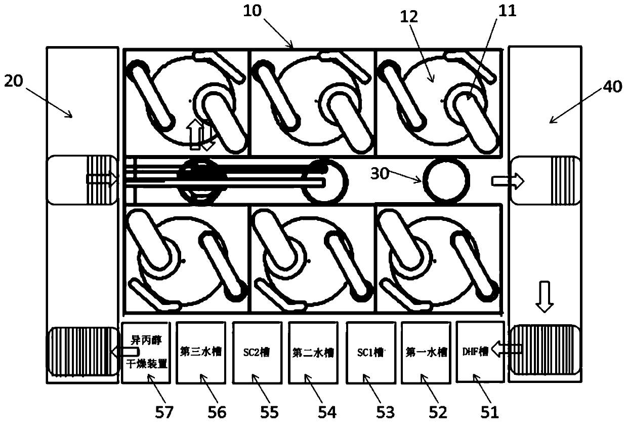
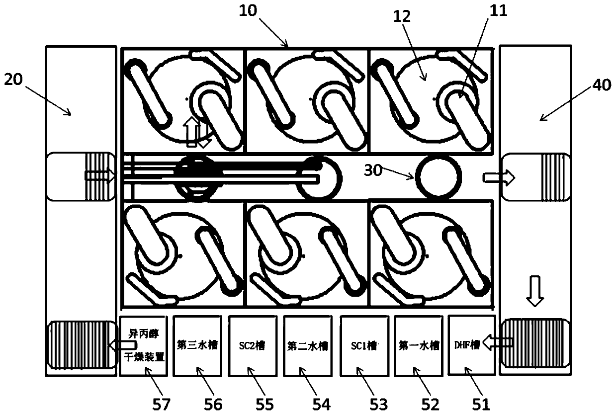
[0023] Such as figure 1 As shown, is a schematic structural diagram of an embodiment of the chemical mechanical planarization equipment of the present invention, and the arrows in the figure indicate the moving direction of the wafer. The chemical mechanical planarization equipment shown in this embodiment comprises: two parallel rows of a total of six polishing units 10, each row is provided with three polishing units 10; For placing wafers to be polished and wafers after cleaning and drying; a row of three loading and unloading tables 30 arranged between two rows of polishing units 10 is used for temporarily placing wafers to be polished and polished wafers, each A loading and unloading platfor...


PUM


Abstract

The invention discloses a chemical mechanical planarization device. The chemical mechanical planarization device comprises multiple rows of multiple polishing units; a transferring platform arranged on one side of the multiple rows of polishing units, at least one row of multiple loading and unloading platforms arranged between two adjacent rows of polishing units, at least one row of cleaning anddrying units parallel to the multiple rows of polishing units, a conveying unit arranged on the other side of the multiple rows of polishing units and a mechanical arm for fetching and placing wafers, wherein the transferring platform is used for holding to-be-polished wafers and cleaned and dried wafers, the loading and unloading platforms are used for temporarily holding the to-be-polished wafers and the polished wafers, the conveying unit is used for conveying the polished wafers to one side of the cleaning and drying units. The chemical mechanical planarization device simplifies the two technology steps of chemical mechanical planarization and wet process cleaning into one step and can achieve dry feeding and dry discharging of the wafers. The chemical mechanical planarization devicedoes not need the extra cleaning equipment adopted after polishing, reduces the occupied area of a purification chamber of by an independent chemical mechanical planarization device and an independentwet process cleaning device and simplifies the technological process.

Description

technical field [0001] The invention relates to the field of equipment for manufacturing semiconductor integrated circuit chips, in particular to a chemical mechanical planarization equipment. Background technique [0002] At present, in the existing semiconductor production technology field, the polishing unit and the acid tank cleaning process equipment are separated, and the polished wafers in a wet state need to be transported to the acid tank cleaning process equipment through the transmission unit, which has long strokes and high efficiency. The shortcomings of low cost and complex process constitute an obstacle to the batch planarization of wafers. At the same time, the existing separate equipment is not conducive to the intelligent transformation of the production process, and cannot coordinate the cooperation between various equipment in the processing process; the waiting time of wafers is increased in the gap between different processing processes, which further c...

Claims


Application Information

Patent Timeline
Patent Type & Authority Applications(China)
IPC IPC(8): B24B37/04B24B37/34H01L21/67
CPCB24B37/04B24B37/34B24B37/345H01L21/67023H01L21/67034
Inventor 顾海洋杨思远
Owner HANGZHOU ZHONGGUI ELECTRONICS TECH CO LTD
Learn More