
High-performance end cover for polypropylene film capacitor

A polypropylene film and capacitor technology, used in film/thick film capacitors, fixed capacitor terminals, laminated capacitors, etc. Improved yield and reliability, improved corrosion resistance, and excellent electrical conductivity

Pending Publication Date: 2019-07-19
WUXI HONGGUANG CAPACITOR
View PDF5 Cites 2 Cited by
  • Summary
  • Abstract
  • Description
  • Claims
  • Application Information

AI Technical Summary

Problems solved by technology

Traditional polypropylene film capacitors use iron solder tab lead-out end caps as capacitor end caps. This end cap is a mature product in the market, so it is easy to purchase and has sufficient output. However, the end cap has solder tab leads that are prone to rust in high-humidity environments. , that is, poor corrosion resistance; the leading end of the soldering piece is susceptible to displacement, twisting, bending, breaking, falling off, etc. by external forces; The reliability brings great hidden dangers
In addition, the iron solder tab lead-out end cover commonly used in the polypropylene film capacitor industry is limited by its structure, and the withstand voltage between the two lead-out terminals can only ensure 4000VAC, which cannot meet the demand for polypropylene film capacitors in high-voltage fields such as substations for the time being.
Due to the above limitations, the iron solder tab lead-out end caps used in traditional polypropylene film capacitors have been difficult to meet the performance requirements of polypropylene film capacitors in emerging fields such as substations and testing equipment in harsh environments.

Method used


Image

  • High-performance end cover for polypropylene film capacitor
  • High-performance end cover for polypropylene film capacitor
  • High-performance end cover for polypropylene film capacitor

Examples


Embodiment Construction

[0020] Below the present invention will be further described in conjunction with the embodiment in the accompanying drawing:

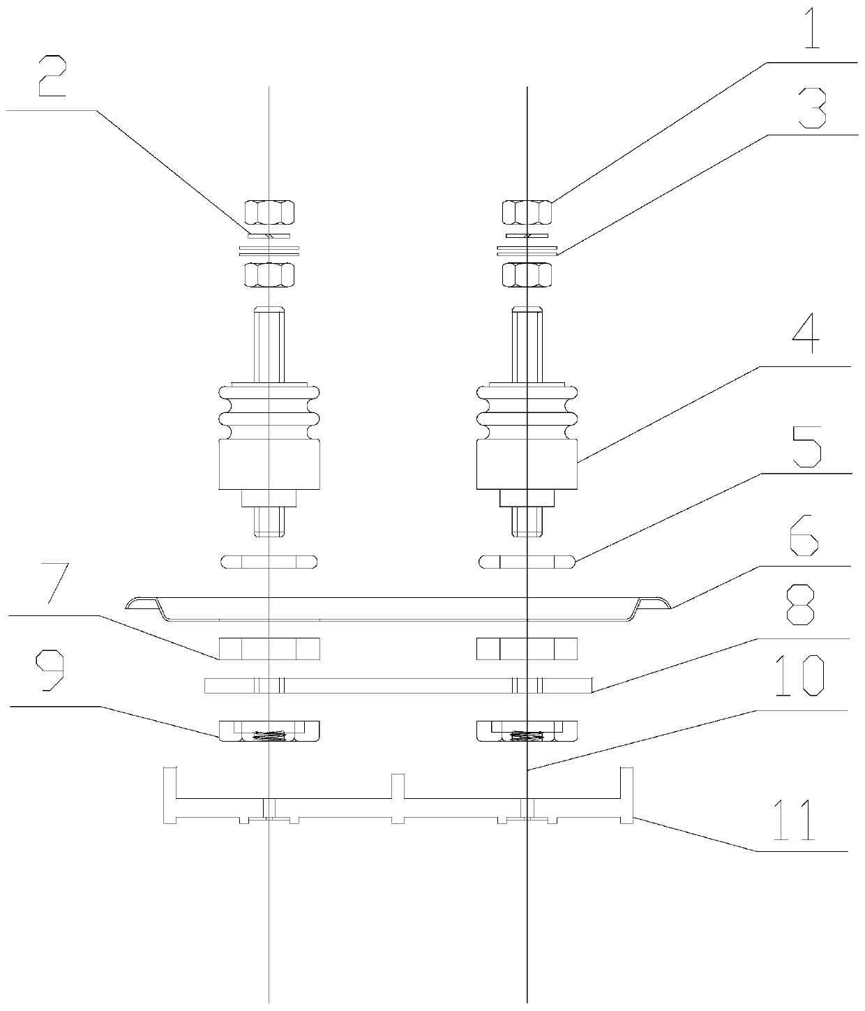
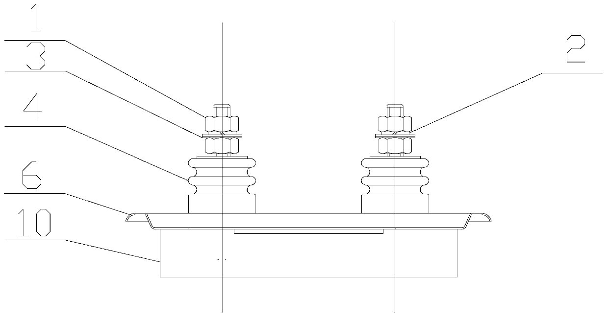
[0021] Such as figure 1 As shown, an end cap for a polypropylene film capacitor, including a mounting nut 1, a mounting spring washer 2, a mounting gasket 3, a bolt lead-out 4, a sealing ring 5, a tinplate sheet 6, a sealing gasket 7, and insulating cardboard 8. Hexagon nut 9, explosion-proof copper wire 10, explosion-proof block 11 and oil injection hole 12 and other parts.

[0022] Among them, the installation nut 1, the installation spring washer 2 and the installation gasket 3 are screwed into the nut at the upper end of the bolt outlet 4 in turn, and the sealing ring 5 is installed in the inner circular groove of the insulating bottom on the bolt outlet 4, and the installation nut 1 is installed. , Install the spring washer 2, the installation gasket 3 and the bolt lead-out end 4 of the sealing ring 5 through the corresponding hexagonal hole on t...


PUM


Abstract

The invention relates to a high-performance end cover for a polypropylene film capacitor. According to the end cover, mounting screw caps, mounting spring washers and mounting gaskets are screwed intonuts at the upper ends of bolt lead-out ends in sequence; sealing rings are mounted in inner circular clamping grooves in the bottoms of insulators on the bolt lead-out ends; the bolt lead-out ends are connected with a tinplate sheet; sealing gaskets are mounted on hexagonal insulating columns of the bolt lead-out ends penetrating through the tinplate sheet; an insulating paper plate sleeves thebolt leading-out ends and are positioned below the sealing gaskets; and the bolt lead-out ends, the sealing rings, the tinplate sheet, the sealing gaskets, the insulating paper plate and hexagonal screw caps are fixed together, then elbow bends at the upper ends of explosion-proof copper wires are welded to the centers of nuts at the lower ends of the bolt lead-out ends, and the lower ends of theexplosion-proof copper wires penetrate into corresponding holes of an explosion-proof block and then are compressed and cut. The end cover is beneficial to the improvement of the long-term service life and reliability of the polypropylene film capacitor, and has the characteristics of high pressure resistance, corrosion resistance, excellent sealing performance and stable performance.

Description

technical field [0001] The invention relates to a high-performance end cover for a polypropylene film capacitor, which can meet the demand for polypropylene film capacitors in high-voltage fields such as substations, and belongs to the technical field of capacitor elements. Background technique [0002] The end cap is one of the important substrates for the production of polypropylene film capacitors, and its structure and performance affect the performance of the capacitor to the greatest extent. Therefore, improving the structure and performance of the end cap is one of the main ways to solve this problem. Traditional polypropylene film capacitors use iron solder tab lead-out end caps as capacitor end caps. This end cap is a mature product in the market, so it is easy to purchase and has sufficient output. However, the end cap has solder tab leads that are prone to rust in high-humidity environments. , that is, poor corrosion resistance; the leading end of the soldering p...

Claims


Application Information

Patent Timeline
Patent Type & Authority Applications(China)
IPC IPC(8): H01G4/002H01G4/224H01G4/236H01G4/33
CPCH01G4/33H01G4/224H01G4/236H01G4/002
Inventor 周定毅匡永正赵志明唐晓雯
Owner WUXI HONGGUANG CAPACITOR
Learn More