High tomography and anti-scatter laser differential confocal tomography method and device
A differential confocal and anti-scattering technology, applied in the direction of determining the optical axis, determining the position of the lens, testing optical performance, etc., can solve problems such as constraints, hindering the adaptability of the interference fixed-focus measurement method, and difficulty in realizing fast fixed-focus measurement
- Summary
- Abstract
- Description
- Claims
- Application Information
AI Technical Summary
Problems solved by technology
Method used
Image
Examples
Embodiment 1
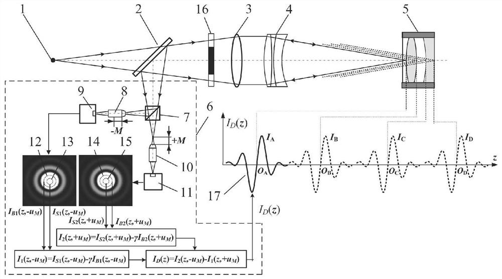
[0066] as attached Figure 8 As shown, a high tomography, anti-scattering laser differential confocal tomography fixed focus device, including a laser 29, a microscope objective lens 30, a pinhole 31, and a polarizing beam splitter 25 placed in the direction of the outgoing light behind the pinhole 31 in sequence , a quarter-wave plate 26, a beam splitter 2, an annular pupil 16, a collimator lens 3 and a measurement objective 4, also including a pre-focus microscopic objective 8 placed in the reflection direction of the beam splitter 2, a pre-focus CCD detection Device 9, post-focus microscope objective lens 10, post-focus CCD detector 11, pre-focus large virtual pinhole detection area 12, pre-focus small virtual pinhole detection area 13, post-focus large virtual pinhole detection area 14, post-focus small The horizontal subtraction differential confocal detection system 6 composed of virtual pinhole detection field 15, and the direction of the transmitted optical axis of the...
Embodiment 2
[0089] Such as Figure 9 As shown, a high tomography, anti-scattering laser differential confocal tomography fixed focus device, its measurement steps are the same as in embodiment 1, the difference is that the point light source 1 uses a fiber coupler 45 and a fiber point diffraction light source 46 to Generated, and then realize laser differential confocal tomography focusing.
[0090] When the detector composed of the microscope objective lens and CCD has a defocus amount of +M relative to the focus of the collimator, the normalized light field distribution U is obtained at the point detector 3 (x,y,z,M) is:
[0091]
[0092] where u M is the normalized defocus amount of the detector, and its expression is:
[0093]
[0094] Then at this time in the large-size virtual pinhole v B The confocal curve obtained by the above processing can be expressed as:
[0095]
[0096] in the small virtual pinhole v S The confocal curve obtained by the above processing can be...
PUM
 Abstract
Description
Claims
Application Information
 - R&D
- Intellectual Property
- Life Sciences
- Materials
- Tech Scout
- Unparalleled Data Quality
- Higher Quality Content
- 60% Fewer Hallucinations
Browse by: Latest US Patents, China's latest patents, Technical Efficacy Thesaurus, Application Domain, Technology Topic, Popular Technical Reports.
© 2025 PatSnap. All rights reserved.Legal|Privacy policy|Modern Slavery Act Transparency Statement|Sitemap|About US| Contact US: help@patsnap.com


