Connection pipe structure, organ perfusion chamber and bio-artificial liver system
A technique of taking over the structure and organ perfusion, which is applied in the field of medical devices, can solve the problems of increased liver ischemia time and decreased liver vitality in vitro, and achieve the effect of maintaining vitality, simple structure and convenient structure
- Summary
- Abstract
- Description
- Claims
- Application Information
AI Technical Summary
Problems solved by technology
Method used
Image
Examples
Embodiment 1
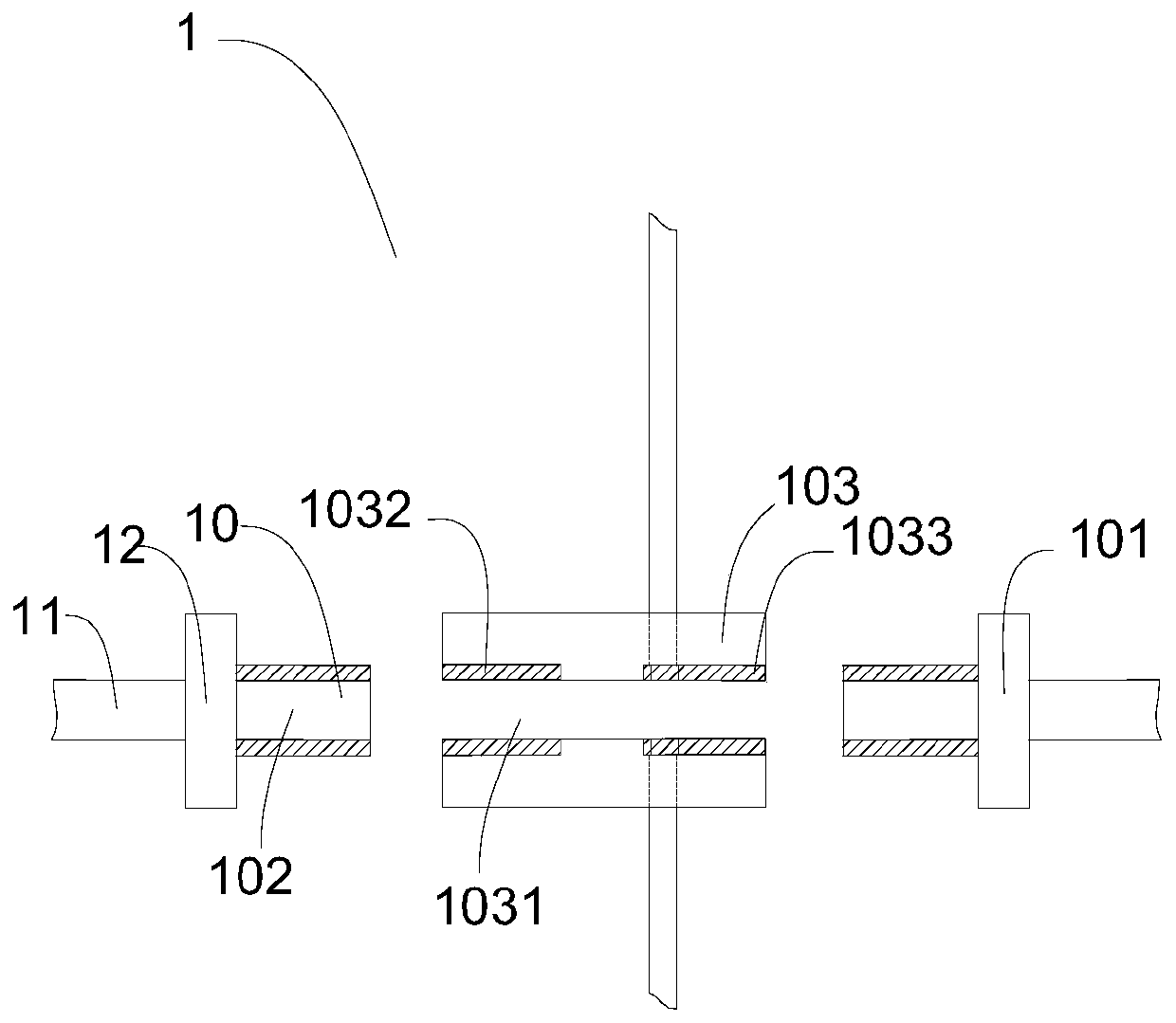
[0046] see figure 1 , a connecting pipe structure 1, including a first joint 101 and a second joint 102 whose ends are set as the connecting end 10, and a joint fixing clip 103 for the connecting end 10 to engage, and the joint fixing clip 103 is provided with The two openings communicate with each other to form a connecting channel 1031 leading through the first connector 101 and the second connector 102 respectively. The shape of the engaging channel 1031 matches the shape of the first joint 101 and the second joint 102 . The engagement channel 1031 is engaged with the first connector 101 and / or the second connector 102 in a tight fit, and the tight fit includes any one of the following: interference fit, screw fit, snap fit.
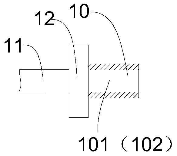
[0047] combine figure 2 The end of the first joint 101 and the second joint 102 away from the connection end 10 is set as the pipeline interface end 11, which is used to connect the pipelines of other devices and equipment systems according to the ...
Embodiment 2
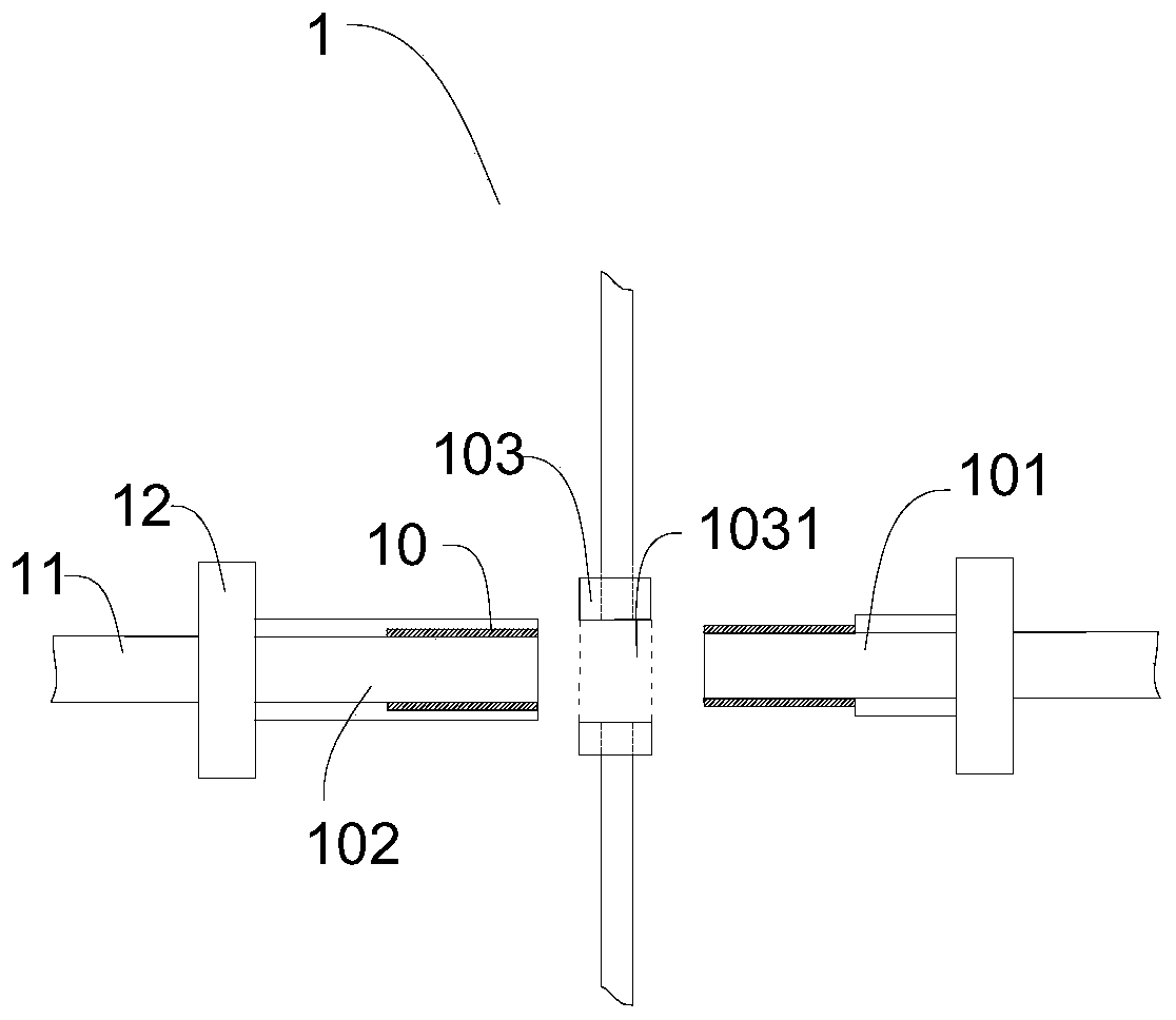
[0055] see image 3 , a connection structure 1, which is different from the connection structure 1 in Embodiment 1 in that: the two openings of the joint channel 1031 pass through coaxially, and the joint fixing clip 103 is made of elastic material. The first joint 101 and the second joint 102 are respectively inserted into two ends of the joint fixing position 103, and their relative positions are fixed by the joint fixing position 103 made of the elastic material. In addition, the connecting ends 10 of the first joint 101 and the second joint 102 are provided with a tight fitting structure nested and connected to each other, so as to realize the Mutual docking at 1031 . The inner wall of the joint channel is smooth, or the inner wall of the joint channel is provided with a gasket layer, so as to realize fast and tight fit between the first joint 101 and the second joint 102 . The tight fit structure of the first joint 101 and the second joint 102 has the same length, so as...
Embodiment 3
[0060] see Figure 5 with Figure 6 , a liver perfusion chamber 2, comprising a chamber body 201, a chamber cover 202 arranged on the top of the chamber body 201, and a connection structure 1 connected to the chamber body 201.
[0061] The connecting pipe structure 1 is fixed to the side wall of the cabin body 201 through the joint fixing position 103, and the first joint 101 is defined in the joint fixing position 103 inside the cabin body 201. On the outside of the cabin body 201 is the second joint 102 . Preferably, the first connector 101 and the second connector 102 are made of disposable sterile materials.
[0062] The liver perfusion chamber 2 further includes a supporting platform 204 disposed inside the chamber 201 and a plurality of supporting platform fixing parts 203 disposed on the inner side wall of the chamber 201 and used to fix the supporting platform 204 . Preferably, the supporting platform fixing part 203 can provide a fixed support point for the support...
PUM
 Abstract
Description
Claims
Application Information
 - Generate Ideas
- Intellectual Property
- Life Sciences
- Materials
- Tech Scout
- Unparalleled Data Quality
- Higher Quality Content
- 60% Fewer Hallucinations
Browse by: Latest US Patents, China's latest patents, Technical Efficacy Thesaurus, Application Domain, Technology Topic, Popular Technical Reports.
© 2025 PatSnap. All rights reserved.Legal|Privacy policy|Modern Slavery Act Transparency Statement|Sitemap|About US| Contact US: help@patsnap.com


