
Pixel driving circuit, pixel driving method and display device

A pixel drive circuit and drive circuit technology, applied to static indicators, instruments, etc., can solve problems such as the inability to guarantee the output characteristics of micro light-emitting diodes, color shift, etc.

Active Publication Date: 2019-07-12
BOE TECH GRP CO LTD
View PDF4 Cites 57 Cited by
  • Summary
  • Abstract
  • Description
  • Claims
  • Application Information

AI Technical Summary

Problems solved by technology

[0005] The main purpose of the present invention is to provide a pixel driving circuit, a pixel driving method, and a display device. When the existing pixel driving circuit using Micro LED is working, it cannot guarantee the output characteristics of the micro light-emitting diode at low gray levels. There will be a problem of color shift when the level changes

Method used


Image

  • Pixel driving circuit, pixel driving method and display device
  • Pixel driving circuit, pixel driving method and display device
  • Pixel driving circuit, pixel driving method and display device

Examples


Embodiment Construction

[0084] The following will clearly and completely describe the technical solutions in the embodiments of the present invention with reference to the accompanying drawings in the embodiments of the present invention. Obviously, the described embodiments are only some, not all, embodiments of the present invention. Based on the embodiments of the present invention, all other embodiments obtained by persons of ordinary skill in the art without making creative efforts belong to the protection scope of the present invention.

[0085] The transistors used in all embodiments of the present invention may be triodes, thin film transistors or field effect transistors or other devices with the same characteristics. In the embodiment of the present invention, in order to distinguish the two poles of the transistor except the control pole, one pole is called the first pole, and the other pole is called the second pole.

[0086] In actual operation, when the transistor is a triode, the contr...


PUM


Abstract

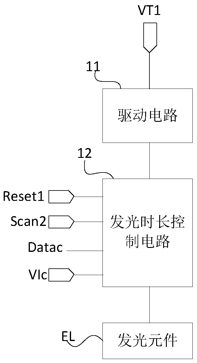
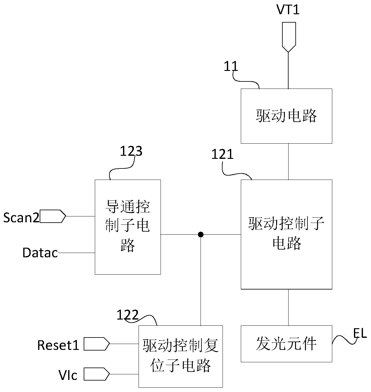
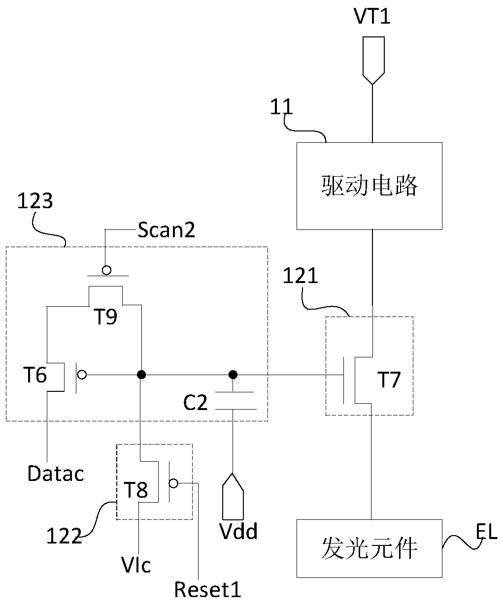
The invention provides a pixel driving circuit, a pixel driving method and a display device. The pixel driving circuit comprises a driving circuit and a light-emitting duration control circuit. A first end of the driving circuit is connected with a first voltage end, a second end of the driving circuit is connected with the light-emitting element through the light-emitting duration control circuit, and the driving circuit is used for controlling the first end and the second end to be communicated under the control of the voltage of the control end of the driving circuit; and under the controlof the first reset signal and the control scanning signal, the light-emitting duration control circuit switches on or switches off the connection between the second end of the driving circuit and thelight-emitting element according to the control data voltage and the control starting voltage so as to control the light-emitting duration of the light-emitting element. The gray scale is jointly modulated through the driving current and the light emitting time, the output characteristic of the micro light emitting diode under the low gray scale can be guaranteed, and the color cast phenomenon generated when the gray scale of the micro light emitting diode changes is avoided.

Description

technical field [0001] The present invention relates to the field of display technology, in particular to a pixel driving circuit, a pixel driving method and a display device. Background technique [0002] Compared with organic light-emitting diodes (OLED), micro light-emitting diodes (Micro LEDs) have higher efficiency, lower power consumption, and higher reliability, and may become new display products in the future. Most of the existing Micro LEDs are formed on a substrate with a driving circuit by transfer printing technology, and the driving circuit drives the Micro LED to realize light emission and display. [0003] At low current density, the efficiency of Micro LED will decrease as the current density decreases. If current density is used to modulate gray scale, low gray scale will correspond to low current density, and its efficiency will decrease. Moreover, as the current density changes, the color coordinates of the Micro LED will change, that is to say, the col...

Claims


Application Information

Patent Timeline
Patent Type & Authority Applications(China)
IPC IPC(8): G09G3/32
CPCG09G3/32G09G3/3233G09G2310/0262G09G2300/0819G09G2300/0852G09G2300/0861G09G2310/061G09G2310/0243G09G2310/067G09G2230/00G09G2300/0426G09G2310/027G09G2310/0278
Inventor 杨盛际陈小川王辉卢鹏程黄冠达
Owner BOE TECH GRP CO LTD
Learn More