
Resonance suppression method and resonance adaptive control method and device based on resonance suppression method

An adaptive control and resonance suppression technology, applied in the direction of reducing/preventing power oscillation, photovoltaic power generation, single-net parallel feeding arrangement, etc., can solve problems such as increasing system loss, reducing system efficiency, and failing to ensure grid friendliness, etc. Guarantee stability, guarantee output characteristics, overcome the effect of grid friendliness

Inactive Publication Date: 2016-03-16
JIANGSU GOODWE POWER SUPPLY TECHNOLOGY CO LTD
View PDF3 Cites 0 Cited by
  • Summary
  • Abstract
  • Description
  • Claims
  • Application Information

AI Technical Summary

Problems solved by technology

The second case is that when multiple inverters are working in parallel, there is a common impedance at the output grid-connected end, which causes multi-machine resonance between parallel inverters
Therefore, the phenomenon of grid-connected resonance has certain randomness
[0004] Therefore, on the one hand, the existing technology may affect the filtering performance of the inverter, on the other hand, it will also increase the system loss and reduce the system efficiency, and the resonance suppression technology often sacrifices the output characteristics of the inverter. Grid friendliness cannot be guaranteed
Therefore, the existing technology cannot meet the grid-connected requirements of various types of grids at the same time

Method used


Image

  • Resonance suppression method and resonance adaptive control method and device based on resonance suppression method
  • Resonance suppression method and resonance adaptive control method and device based on resonance suppression method

Examples


Embodiment Construction

[0022] The present invention will be further described below in conjunction with the embodiments shown in the accompanying drawings.

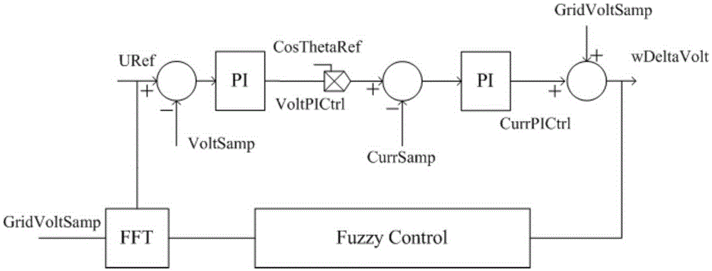
[0023] A resonance suppression method applied to photovoltaic grid-connected inverters to suppress the resonance generated by the grid-connected inverters is: performing fuzzy control on the voltage of the photovoltaic grid-connected inverters connected to the grid to eliminate system resonance. Specifically, first of all, judge whether the photovoltaic grid-connected inverter is in the resonant mode, because resonance will cause the grid voltage to oscillate, so by judging whether the grid voltage is oscillating, it can be distinguished whether the system is in a resonant state, so the photovoltaic grid-connected inverter The voltage connected to the power grid is sampled and analyzed by Fourier. If the content of high-frequency components in the voltage is analyzed to be too high, it is judged to be a resonance mode. At this time, fuzzy contr...


PUM


Abstract

The invention relates to a resonance suppression method. The resonance suppression method comprises the following steps of performing fussy control on a voltage of a power grid accessed by a photovoltaic grid-connected inverter and eliminating system resonance. A resonance adaptive control method based on the resonance suppression method comprises the following steps: judging whether the photovoltaic grid-connected inverter is under a resonant mode; if so, then adopting the resonance suppression method to eliminate the system resonance; if not, then adopting a PI double loop control method to control the voltage. A resonance adaptive control device comprises a judgment module used for judging whether the photovoltaic grid-connected inverter is under the resonant mode; a fussy control branch used for performing fussy control on the voltage of the power grid to eliminate the system resonance; and a conventional grid-connected branch used for performing conventional grid-connected control on the voltage of the power grid. The scheme of the invention can automatically distinguish whether a grid-connected system is resonant and use different control strategies, which can not only guarantee an output characteristic under a normal grid-connected condition, but can also guarantee the stability of the system under a high-impedance state and other resonant states.

Description

technical field [0001] The invention belongs to the field of photovoltaic power generation, and in particular relates to a method and a device applied to a situation where a photovoltaic inverter generates resonance under the conditions of high impedance of a power grid or parallel connection of multiple machines. Background technique [0002] For photovoltaic grid-connected inverters, resonance is a problem that needs to be solved urgently. The occurrence of resonance is likely to cause the inverter to go off-grid, resulting in great economic losses. The resonance of the photovoltaic grid-connected inverter is roughly caused by two situations: the first situation is that there is a high impedance in the line from the inverter to the power grid, which forms an LCL network with the filter inductance and capacitance of the inverter itself, and the output current of the inverter When the high-order harmonics contained are exactly the same as the resonant frequency of the LCL ne...

Claims


Application Information

Patent Timeline
Patent Type & Authority Applications(China)
IPC IPC(8): H02J3/38H02J3/24
CPCY02E10/56
Inventor 舒婕妤
Owner JIANGSU GOODWE POWER SUPPLY TECHNOLOGY CO LTD
Learn More