
Wet joint connection design of prefabricated concrete beam

A technology of prefabricated concrete and wet joints, applied in bridge construction, bridges, bridge parts, etc., can solve the problems of complex shape of reserved steel bars, difficulty in installation of beams and slabs on site, inconvenient processing and construction, etc., to achieve convenient construction and structure Simple and cost-effective construction

Inactive Publication Date: 2019-07-12
THE 5TH CONSTR COMPANY LTD OF CHINA RAILWAY 15TH BUREAU GRP +1
View PDF7 Cites 10 Cited by
  • Summary
  • Abstract
  • Description
  • Claims
  • Application Information

AI Technical Summary

Problems solved by technology

(1) The structural shape of the reserved steel bars in the wet joints is too complicated, which is not convenient for processing and construction; Insufficient precision leads to conflicts between beam and slab steel bars on both sides of the wet joint, making it difficult to install the on-site beam and slab. Secondly, from the existing actual construction situation, the reserved steel bars on both sides of the prefabricated beam and slab are usually welded in the wet joint connection. A large bridge often There are thousands of meters or even thousands of wet joints, and the construction cost is huge if calculated as one weld every 30cm

Method used


Image

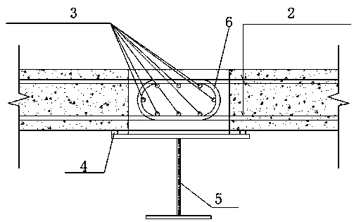
  • Wet joint connection design of prefabricated concrete beam
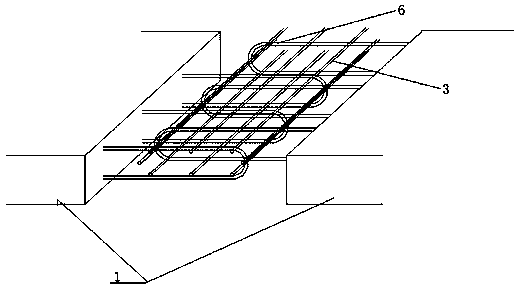
  • Wet joint connection design of prefabricated concrete beam
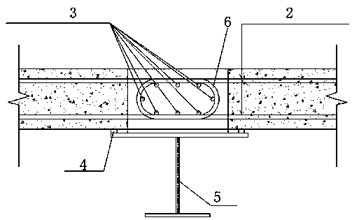
  • Wet joint connection design of prefabricated concrete beam

Examples


Embodiment Construction

[0020] The present invention is described in conjunction with accompanying drawing and specific embodiment:

[0021] Such as figure 1 As shown, a wet joint connection design of precast concrete beams, the wet joint is formed by the reserved gap between two adjacent precast concrete beam slabs 1; The corresponding precast concrete beam slabs protrude, and the steel bars at the ends are bent into a semi-circular shape; the semi-circular steel bars 6 reserved for two adjacent precast concrete beam slabs intersect with each other at the wet joints, forming a structure for bearing complex stresses. In the annular area of ​​the core concrete, the semi-annular reserved steel bar of each precast concrete beam slab is used as the U-shaped stirrup of the core concrete, and the opening direction of the U-shaped stirrup corresponds to the setting of the corresponding precast concrete beam slab; two adjacent precast concrete beams The U-shaped stirrups of the concrete beam slab are stagge...


PUM


Abstract

The invention belongs to the technical field of civil engineering, and particularly relates to wet joint connection design of a prefabricated concrete beam. According to the wet joint connection design of the prefabricated concrete beam, and a wet joint is formed by a reserved gap between two adjacent prefabricated concrete beam plates; embedded steel bars in the prefabricated concrete beam platesextend to the corresponding prefabricated concrete beam plates, and the end part steel bars are bent into a semi-annular shape; the semi-annular shape steel bars reserved by the adjacent two prefabricated concrete beam plates interlace with each other in the wet joint position to form an annular area used for carrying core concrete, and the semi-annular shape steel bars of each prefabricated concrete beam plate is used as U-shaped hoop bars for carrying the core concrete; and the U-shaped hoop bars of the adjacent two prefabricated concrete beam plates are interlaced into circumferential hoopbars; and longitudinal steel bars are arranged in the circumferential hoop bars, and the longitudinal steel bars are arranged on the corresponding circumferential hoop bars in an attached mode. The wet joint connection design of the prefabricated concrete beam greatly saves the construction cost, reduces the engineering cost, and has the characteristics of simple structure and convenient construction.

Description

technical field [0001] The invention belongs to the technical field of civil engineering, and in particular relates to a wet joint connection design of prefabricated concrete beams. Background technique [0002] It can be seen from the construction of existing steel-concrete composite girder bridges (including composite girder cable-stayed bridges) that steel-concrete composite bridge decks are usually assembled from prefabricated concrete slabs in early beam yards. After completion, the pouring of wet joints in the post-construction of the bridge accounts for a considerable amount of work, and the reinforcement arrangement and connection treatment of wet joints are the key to ensure that the wet joints can reliably connect the two sides of the bridge at the top of the steel beam. The connection of precast concrete slabs formed early into the whole made or breaks the project. [0003] Judging from the current existing wet joint structure, there are the following deficiencie...

Claims


Application Information

Patent Timeline
IPC IPC(8): E01D19/06
CPCE01D19/067
Inventor 杨怀宇袁鹰陈竞尧李剑恒马辉杰张心贤宋增强张率兵张莉王淑龙邹平王霖周中可陶方根周林刚任成俊
Owner THE 5TH CONSTR COMPANY LTD OF CHINA RAILWAY 15TH BUREAU GRP
Learn More