Eureka AIR delivers breakthrough ideas for toughest innovation challenges, trusted by R&D personnel around the world.

Sponge foaming equipment and working method thereof

A foaming equipment and sponge technology, applied in metal processing and other directions, can solve problems such as affecting the production efficiency of sponges, unable to continuously complete sponge foaming, conveying, cutting, unloading, and low degree of automation.

Pending Publication Date: 2019-07-09
江苏华艺泡棉科技有限公司
View PDF0 Cites 9 Cited by
  • Summary
  • Abstract
  • Description
  • Claims
  • Application Information

AI Technical Summary

Problems solved by technology

Among them, the high-density sponge has many holes and is very full. Because of its good air permeability and elasticity, it is often used to make sound-absorbing cotton, sofa cushions, soft bags and other materials. Sponge hair is usually used in the production of these sponge products. Foaming equipment, the degree of automation of sponge foaming equipment directly affects the production efficiency of sponges and affects the profits of enterprises. Productivity

Method used


Image

  • Sponge foaming equipment and working method thereof
  • Sponge foaming equipment and working method thereof
  • Sponge foaming equipment and working method thereof

Examples


Embodiment 1

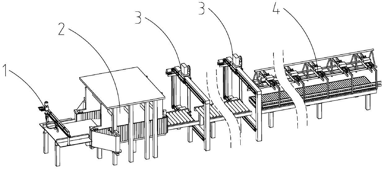
[0054] figure 1 It is a schematic structural diagram of the sponge foaming device of the present invention;

[0055] like figure 1 As shown, a sponge foaming equipment includes a frame, a feeding device 1, a foaming conveying device 2, a heating device, a cutting device 3 and an unloading device 4, wherein,

[0056] The frame is provided with a foaming sponge conveying channel;

[0057] The feeding device 1, the foaming conveying device 2, the cutting device 3 and the unloading device 4 are sequentially arranged along the advancing direction of the foamed sponge in the foamed sponge conveying channel;

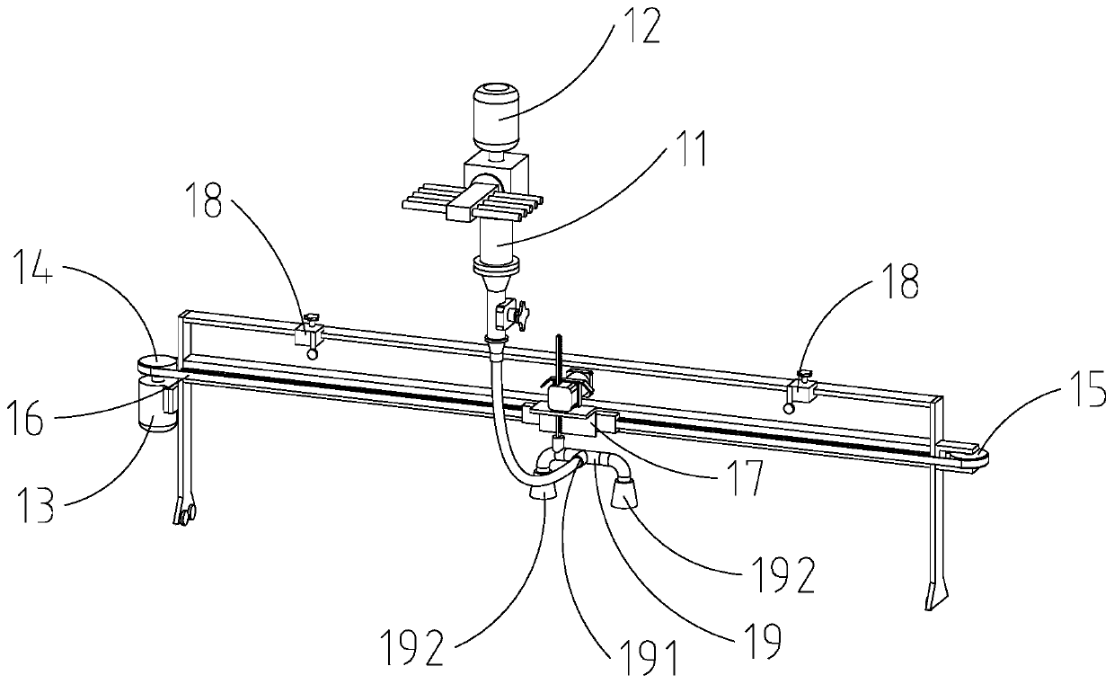
[0058] The feeding device 1 is arranged on the frame, and the feeding device 1 is used for inserting raw materials and stirring the raw materials evenly and then discharging them into the foaming sponge conveying channel, and the raw materials are discharged to the foaming sponge. Foaming begins after the sponge is transported in the channel.

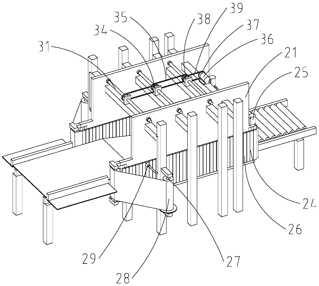
[0059] The foaming conveying ...

Embodiment 2

[0098] A working method of the sponge foaming device as described in Embodiment 1, comprising in the steps of the method:

[0099] The feeding device 1 is connected to the raw material, and the raw material is stirred evenly and then discharged into the foaming sponge conveying channel;

[0100] The raw material is foamed in the foaming sponge conveying channel, and the foaming conveying device 2 clamps and conveys the foaming foam in the foaming sponge conveying channel forward, and the heating device simultaneously treats the foaming foam. The foam sponge is heated to speed up the foaming;

[0101] The cutting device 3 cuts the foamed foam that has been foamed and formed to be conveyed to the cutting device 3 along a direction perpendicular to the advancing direction of the foamed sponge;

[0102] The unloading device 4 is actuated to remove the cut foamed sponge.

[0103] The working principle of the present invention is as follows:

[0104] The feeding device 1 is conne...


PUM


Abstract

The invention discloses sponge foaming equipment. The sponge foaming equipment comprises a frame, a feeding device, a foaming conveying device, a heating device, a cutting device and an unloading device, wherein a foaming sponge conveying channel is arranged on the frame; the feeding device, the foaming conveying device, the cutting device and the unloading device are sequentially arranged along the advancing direction of the foaming sponges in the foaming sponge conveying channel; the feeding device is arranged on the frame and is used for accessing raw materials, uniformly stirring the raw materials and unloading the raw materials into the foaming sponge conveying channel; and the foaming conveying device is arranged on the frame and is used for clamping and conveying the foaming spongesbeing foamed in the foaming sponge conveying channel forwards. According to the sponge foaming equipment, the production and processing of the foaming sponges can be automatically completed, the automation degree is high, the production efficiency is high, the product quality is good, the structure is simple, and the operation cost is low.

Description

technical field [0001] The present invention relates to a sponge foaming device and its working method. Background technique [0002] At present, the commonly used sponges are divided into three types: high-density sponge, medium-density sponge and low-density sponge according to their structure. Among them, high-density sponges have many pores and are very full. Because of their good air permeability and elasticity, they are often used as sound-absorbing cotton, sofa cushions, soft bags and other materials. In the production of these sponge products, sponge hair is usually used. Foaming equipment, the degree of automation of the foaming equipment directly affects the production efficiency of the sponge and affects the profit of the enterprise. The existing foaming equipment has a low degree of automation and cannot continuously complete the production processes such as foaming, conveying, cutting, and unloading, which seriously affects Productivity. SUMMARY OF THE INVENT...

Claims


Application Information

Patent Timeline
IPC IPC(8): B29C44/34B26D1/46
CPCB29C44/34B29C44/3415B29C44/3442B26D1/46
Inventor 陈科黄存付李刚
Owner 江苏华艺泡棉科技有限公司
Why Eureka
Eureka Blog
Learn More