Broadside boarding platform device
A platform device and side-side technology, which is applied in the direction of transportation and packaging, cargo handling equipment, passenger handling equipment, etc., can solve the problems that the personal safety of the crew is difficult to guarantee, and the automatic retraction of the boarding platform cannot be realized, so as to save labor costs, The effect of ensuring the personal safety of the crew and improving the degree of automation
- Summary
- Abstract
- Description
- Claims
- Application Information
AI Technical Summary
Problems solved by technology
Method used
Image
Examples
Embodiment 1
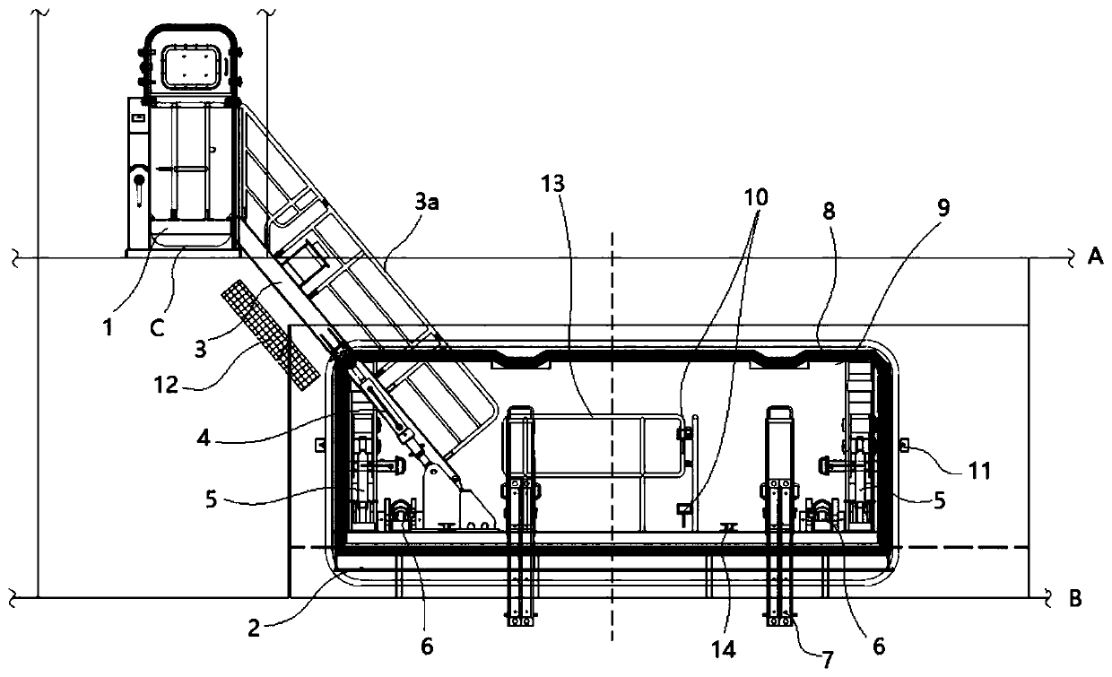
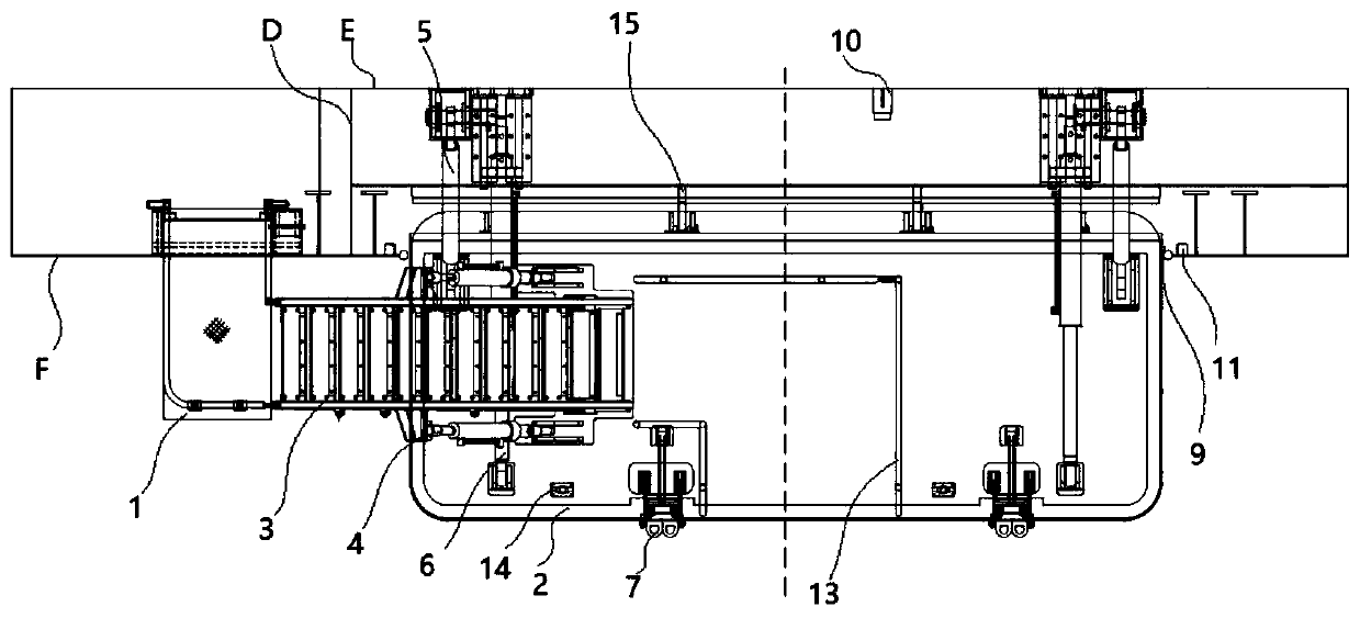
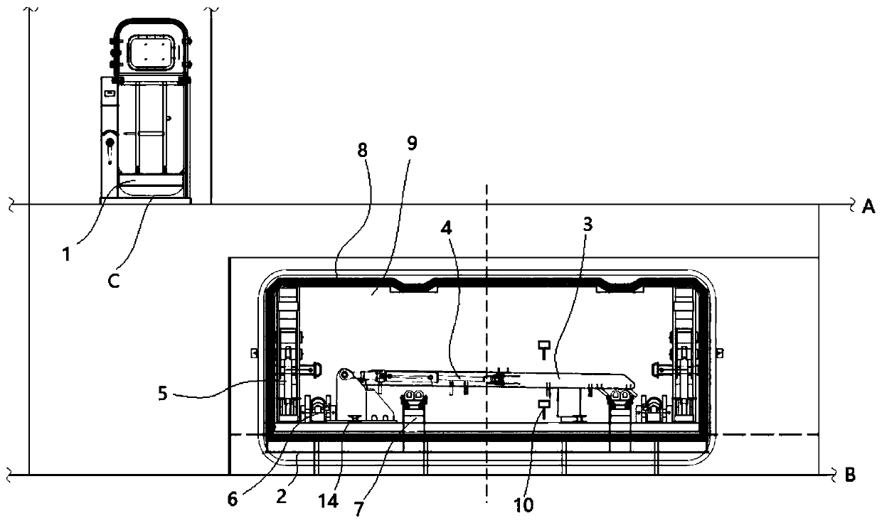
[0041] Such as Figure 1 to Figure 8 As shown, Embodiment 1 discloses a specific implementation of a side boarding platform device, which specifically includes: an upper platform 1 that is rotatably connected to the outer panel F of the hull, and is rotatably connected to the longitudinal bulkhead E through a rotatable connection mechanism 15 Main platform 2, main platform retractable oil cylinder 6, telescopic gangway 3 and gangway lifting oil cylinder 4.
[0042] Specifically, such as figure 2 As shown, the upper platform 1 is set at the opening C of the hull, and the upper platform 1 is located above the main deck A. The position of the upper platform 1 is rotated and switched between the horizontal position and the vertical position. The horizontal position is the plane where the upper platform 1 is located. Parallel to the horizontal plane, the vertical position is that the upper platform 1 is folded on the outer panel F of the hull, that is, the upper platform 1 is rot...
Embodiment 2
[0060] Such as Figure 1 to Figure 8 As shown, Embodiment 2 is based on Embodiment 1. The fixed frame 18a of Embodiment 2 also includes a first step adjustment device. The steps 17 are rotatably connected to the fixed frame body 18a-5. The first step adjustment device includes : the first electric cylinder 18a-2, the first connecting rod 18a-3, some first linkage rods 18a-4, the first electric cylinder 18a-2 is rotatably connected to the first guide groove body 18a-1, the first electric cylinder The free end of the push rod of 18a-2 is rotatably connected to one of the ends of the first connecting rod 18a-3, and the first end of the first linkage rod 18a-4 is rotatably connected to the first connecting rod 18a-3. The second end of the linkage rod 18a-4 is fixedly connected to the end of the step 17, and several first linkage rods 18a-4 are evenly connected to the first connection rod 18a-3 along the length direction of the first connection rod 18a-3, Moreover, several first l...
Embodiment 3
[0067] Such as Figure 7 As shown, in Embodiment 3, on the basis of Embodiments 1 to 2, four first stiffening plates 19 are provided at the connection between the first limiting plate 20 and the groove bottom of the first guide groove body 18a-1 in Embodiment 3. , four first stiffening plates 19 are arranged on the end surface of the first limiting plate 20 close to the first limiting pulley 18 a - 6 , and the four first stiffening plates 19 are uniformly arranged on the first limiting plate 20 .
[0068] Such as Figure 8 As shown, four second stiffening plates 21 are arranged at the connection between the second limiting plate 22 and the groove bottom of the second guide groove body 18b-1, and the four second stiffening plates 21 are arranged near the second limiting plate 22. On the end surface of the second limiting pulley 18b-6, four second stiffening plates 21 are evenly arranged on the second limiting plate 22.
[0069] The strength of the first limiting plate 20 is s...
PUM
 Abstract
Description
Claims
Application Information
 - Generate Ideas
- Intellectual Property
- Life Sciences
- Materials
- Tech Scout
- Unparalleled Data Quality
- Higher Quality Content
- 60% Fewer Hallucinations
Browse by: Latest US Patents, China's latest patents, Technical Efficacy Thesaurus, Application Domain, Technology Topic, Popular Technical Reports.
© 2025 PatSnap. All rights reserved.Legal|Privacy policy|Modern Slavery Act Transparency Statement|Sitemap|About US| Contact US: help@patsnap.com


