
Separation membrane element

A separation membrane and element technology, applied in the field of separation membrane elements, can solve the problems of reduced fluid permeability, separation performance, increased membrane surface concentration, and reduced membrane surface turbulent effect, achieving increased and suppressed membrane surface turbulent effects Effects of concentration polarization, maintenance of fluid permeability and separation performance

Active Publication Date: 2021-08-31
TORAY IND INC
View PDF9 Cites 0 Cited by
  • Summary
  • Abstract
  • Description
  • Claims
  • Application Information

AI Technical Summary

Problems solved by technology

[0010] Although the separation membrane elements described in Patent Document 1 and Patent Document 2 can improve the turbulent flow effect on the membrane surface and suppress concentration polarization, they have the following problems: especially when performing high recovery rate operation (recovery rate: permeate fluid volume vs. In the case of the ratio of the amount of feed fluid supplied to the element), the flow rate of the feed fluid decreases as it approaches the outlet of the feed fluid, so the separated components in the feed fluid are concentrated, and the effect of turbulence on the membrane surface decreases, resulting in a concentration of Increased, fluid permeability, separation performance decreased, easy to produce scale (scaling)

Method used

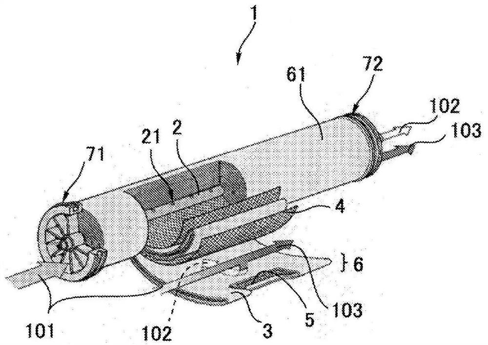
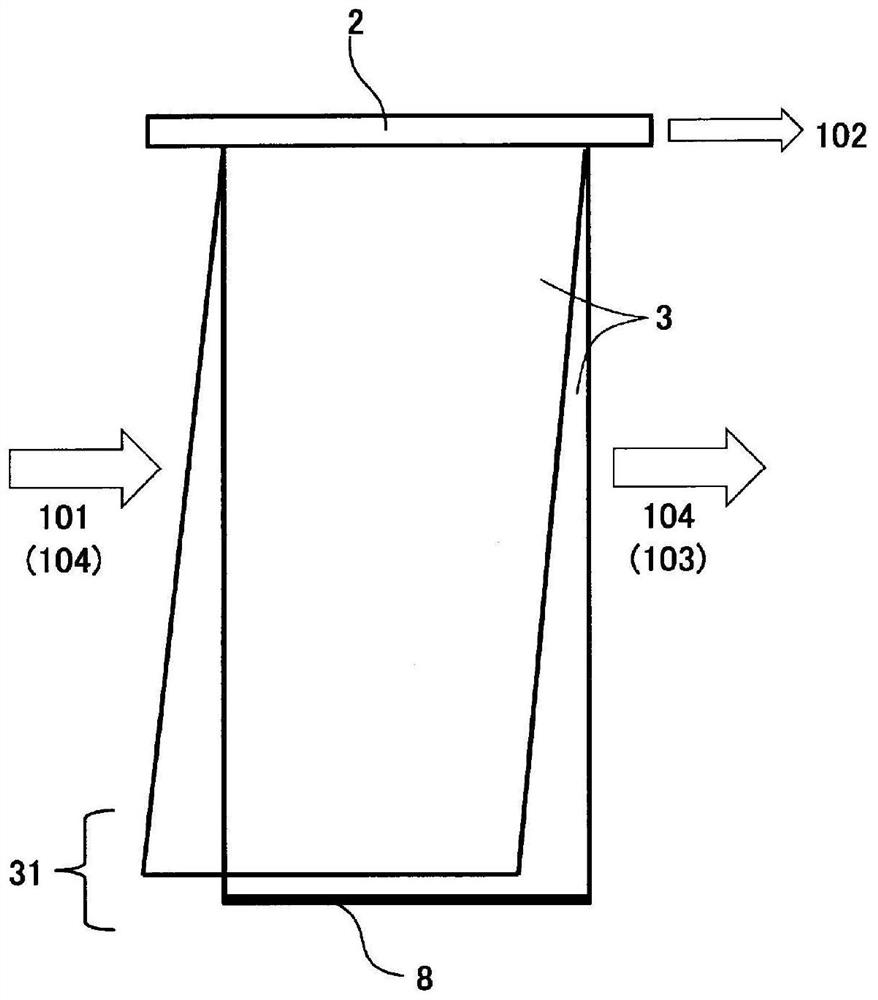
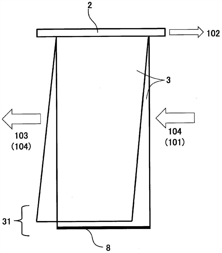

Image

  • Separation membrane element
  • Separation membrane element
  • Separation membrane element

Examples


Embodiment 1

[0152] At room temperature (25°C), a nonwoven fabric composed of polyethylene terephthalate fibers (filament diameter: 1 dtex, thickness: about 0.09 mm, density 0.80 g / cm 3 ) to a thickness of 180 μm by adding a N,N-dimethylformamide solution containing 15.2% by mass of polysulfone, immediately immersing it in pure water for 5 minutes, and then immersing it in warm water at 80°C for 1 minute. A porous support layer (thickness of 0.13 mm) composed of a fiber-reinforced polysulfone support layer.

[0153] Then, the porous support layer was unwound from a roll, immersed in an aqueous solution containing m-PDA of 3.8 mass % for 2 minutes, the support layer was slowly lifted in the vertical direction, and nitrogen gas was blown through an air nozzle to remove excess from the surface of the support layer. Then, the n-decane solution containing 0.175% by mass of tribenzoyl chloride was applied to completely wet the surface, and it was left to stand for 1 minute. Next, in order to re...

Embodiment 2

[0159] A separation membrane element was produced and performance was evaluated in the same manner as in Example 1, except that the number of separation membrane pairs was 5, and the number of separation membrane pairs was changed to 3 pairs of I-type separation membranes and 2 pairs of inverted L-type separation membranes. The results are shown in Table 1.

Embodiment 3

[0161] A separation membrane element was produced in the same manner as in Example 1, except that the number of separation membrane pairs was changed to 3 pairs of I-type separation membranes and one pair of inverted L-type separation membranes, and the performance was evaluated. The results are shown in Table 1.


PUM

PropertyMeasurementUnit
thicknessaaaaaaaaaa
compressive modulusaaaaaaaaaa
thicknessaaaaaaaaaa

Abstract

An object of the present invention is to provide a separation membrane element having high fluid permeability and separation performance. The separation membrane element of the present invention includes a central tube with holes, a plurality of separation membrane pairs formed so that the permeation-side surfaces of the separation membranes having a supply-side surface and a permeation-side surface face each other, and a pair of separation membranes provided on the supply side of the separation membrane pair. The supply-side channel member between the surfaces, and the permeation-side channel member disposed between the permeation-side surfaces of the separation membrane pair, the separation membrane pair is wound around the perforated central tube, the supply-measuring channel member, On the surface of the separation membrane on the supply side, one end face and the other end face in the longitudinal direction of the perforated central tube and the inner periphery in the direction perpendicular to the longitudinal direction of the perforated central tube Two or more of the end faces or ends of the end and the outer peripheral end are respectively open by more than 5%, and the plurality of separation membrane pairs are composed of at least one first separation membrane pair and at least one second separation membrane pair, and the first separation membrane The combination of end surfaces or end portions of the openings in the pair and the second separation membrane pair are different.

Description

technical field [0001] The present invention relates to a separation membrane element for separating components contained in fluids such as liquids and gases. Background technique [0002] In recent years, as a technique for removing ionic substances contained in seawater, salt water, etc., as a process for energy saving and resource saving, a separation method by a separation membrane element is widely used. Separation membranes used in separation methods using separation membrane elements can be classified into fine filtration membranes, ultrafiltration membranes, nanofiltration membranes, reverse osmosis membranes, and forward osmosis membranes based on their pore size and separation function. These membranes are used in the production of potable water from, for example, seawater, brine, and water containing hazardous substances, in the production of ultrapure water for industrial use, and in wastewater treatment and recovery of valuable substances, etc., depending on the...

Claims


Application Information

Patent Timeline
Patent Type & Authority Patents(China)
IPC IPC(8): B01D63/10B01D63/00B32B1/08C02F1/44
CPCB32B1/08B01D63/103C02F1/441C02F2103/08B32B3/30B32B3/08B32B5/26B32B2262/0276B32B27/12B32B27/36B32B27/302B32B5/026B32B2307/51B32B3/266B32B2262/0207B32B2307/732B32B2597/00B32B2262/0223B32B2262/0253B32B27/32B32B5/022B32B5/028Y02A20/141B01D63/1031B01D61/025B01D65/02B01D65/08B01D69/10C02F1/44B01D63/00B01D63/101B01D63/107
Inventor 冈本宜记贾格阿克谢高木健太朗广泽洋帆北出有
Owner TORAY IND INC
Learn More