
MEMS closed-loop accelerometer based on rigidity compensation

An accelerometer and stiffness technology, applied in the direction of velocity/acceleration/shock measurement, acceleration measurement, acceleration measurement using inertial force, etc., can solve the problems of reduced accelerometer sensitivity, poor consistency, processing error and so on

Pending Publication Date: 2019-06-28
四川知微传感技术有限公司
View PDF8 Cites 5 Cited by
  • Summary
  • Abstract
  • Description
  • Claims
  • Application Information

AI Technical Summary

Problems solved by technology

However, due to poor consistency and processing errors in the production process of MEMS accelerometers, the mechanical structure stiffness of the produced accelerometer may be larger than the theoretical design value, resulting in reduced sensitivity of the accelerometer, increased noise, and poor resolution. Rate variation, etc., which will seriously hinder its application in the field of high precision

Method used


Image

  • MEMS closed-loop accelerometer based on rigidity compensation
  • MEMS closed-loop accelerometer based on rigidity compensation
  • MEMS closed-loop accelerometer based on rigidity compensation

Examples


Embodiment Construction

[0023] In order to understand the above-mentioned purpose, features and advantages of the present invention more clearly, the present invention will be further described in detail below in conjunction with the accompanying drawings and specific embodiments. It should be noted that, under the condition of not conflicting with each other, the embodiments of the present application and the features in the embodiments can be combined with each other.

[0024] In the following description, many specific details are set forth in order to fully understand the present invention. However, the present invention can also be implemented in other ways different from the scope of this description. Therefore, the protection scope of the present invention is not limited by the following disclosure. limitations of specific examples.

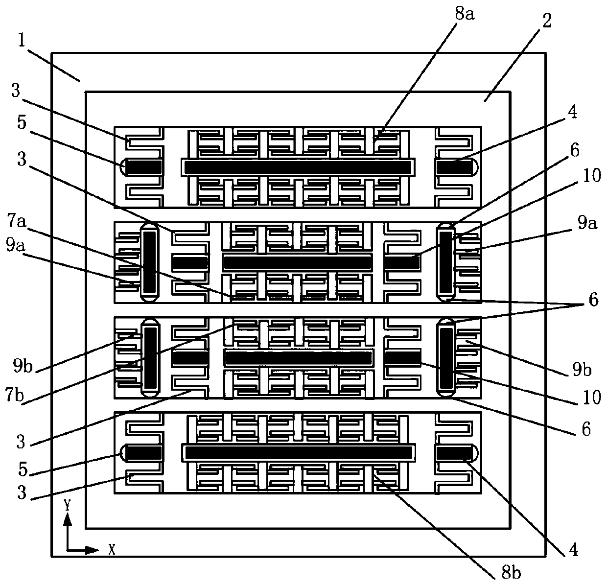
[0025] The invention provides a MEMS closed-loop accelerometer based on stiffness compensation. The features of the accelerometer are: 1. The stiffness compensat...


PUM


Abstract

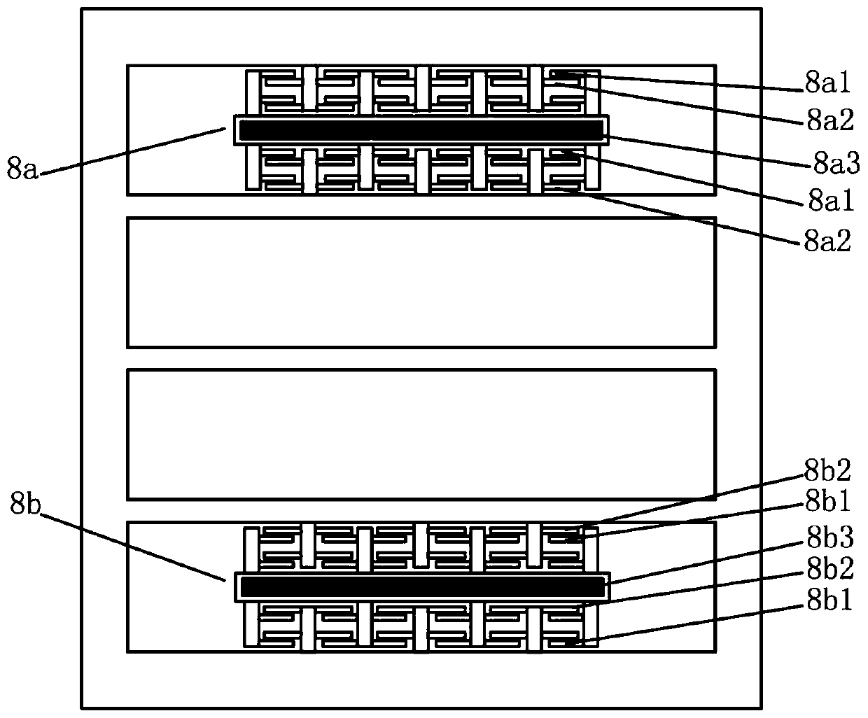
The invention discloses a MEMS closed-loop accelerometer based on rigidity compensation. The MEMS closed-loop accelerometer based on rigidity compensation comprises an upper half part and a lower halfpart which are centrosymmetric along the accelerometer, each of the upper half part and the lower half part comprises a substrate, an anchor point is fixed on each substrate, an insulating layer is arranged on each substrate, each insulating layer is provided with a sensitive device layer, and each sensitive device layer comprises a sensitive mass block, a supporting beam, a force feedback comb tooth unit, a detection comb tooth unit and a rigidity compensation unit; the sensitive mass block of each of the upper half part and the lower half part is provided with a first hollowed-out area anda second hollowed-out area; a supporting beam anchor point, a supporting beam, a detection comb tooth unit anchor point and a detection comb tooth unit are mounted in each first hollowed-out area; a supporting beam anchor point, a supporting beam, a force feedback comb tooth unit, a force feedback comb tooth unit anchor point, a rigidity compensation unit and a rigidity compensation unit anchor point are mounted in each second hollowed-out area; and by the design of a rigidity compensation structure of the accelerometer, the problem of large mechanical rigidity due to processing of a technology can be solved.

Description

technical field [0001] The invention relates to the field of micromechanical MEMS accelerometers, in particular to a MEMS closed-loop accelerometer based on stiffness compensation. Background technique [0002] Micromechanical MEMS accelerometer is a device or device for measuring acceleration, which has a wide range of application requirements in high-precision fields such as industrial control, aviation, aerospace, and military. However, due to poor consistency and processing errors in the production process of MEMS accelerometers, the mechanical structure stiffness of the produced accelerometer may be larger than the theoretical design value, resulting in reduced sensitivity of the accelerometer, increased noise, and poor resolution. Rate variation, etc., which will seriously hinder its application in the field of high precision. Therefore, strategies need to be adopted to compensate for the influence of excessive mechanical stiffness caused by process errors. Contents...

Claims


Application Information

Patent Timeline
IPC IPC(8): G01P15/125G01P15/08B81B7/02B81B7/00
Inventor 雷龙海周骏王龙峰王志山永启
Owner 四川知微传感技术有限公司
Learn More