
Heat pipe

A heat pipe and pipe body technology, applied in indirect heat exchangers, lighting and heating equipment, etc., can solve the problems of complex manufacturing process, high manufacturing cost, poor stability, etc., and achieve simple manufacturing process, material saving, and less welding points. Effect

Inactive Publication Date: 2019-06-25
温岭市雪鹏机械有限公司
View PDF0 Cites 0 Cited by
  • Summary
  • Abstract
  • Description
  • Claims
  • Application Information

AI Technical Summary

Problems solved by technology

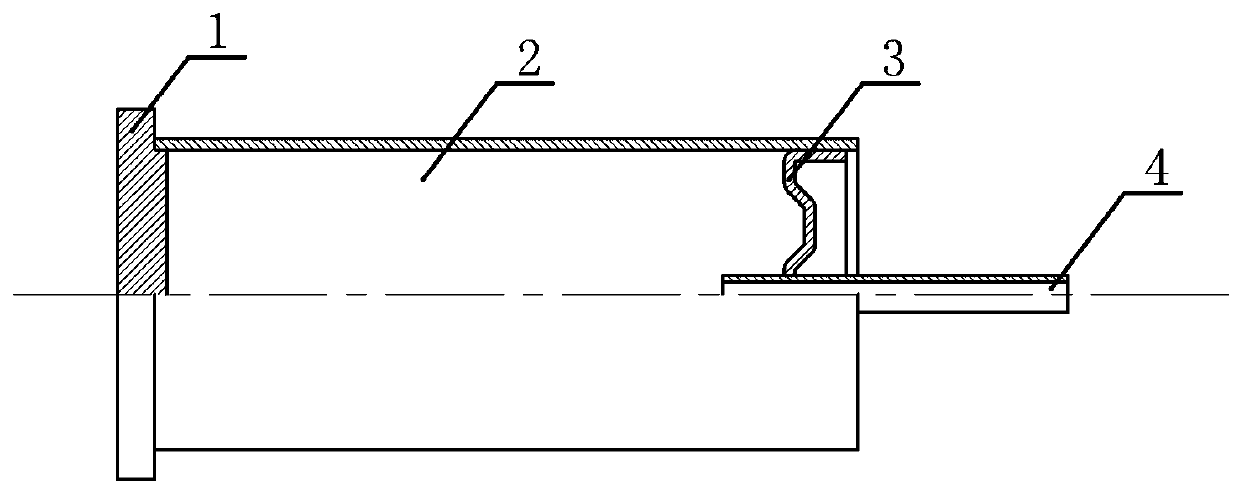
[0004] Since the above-mentioned heat pipe is composed of four independent parts (sealing cap 1, main pipe 2, sealing cap 2 3, and piping 4), it is necessary to accurately position the four independent parts before welding, and it is easy to generate heat during welding, resulting in low yield. Low, complex manufacturing process, high manufacturing cost; and all parts are fixed together by welding, many welding points, poor stability

Method used


Image

  • Heat pipe
  • Heat pipe

Examples


Embodiment Construction

[0020] The following are specific embodiments of the present invention in conjunction with the accompanying drawings to further describe the technical solutions of the present invention, but the present invention is not limited to these embodiments.

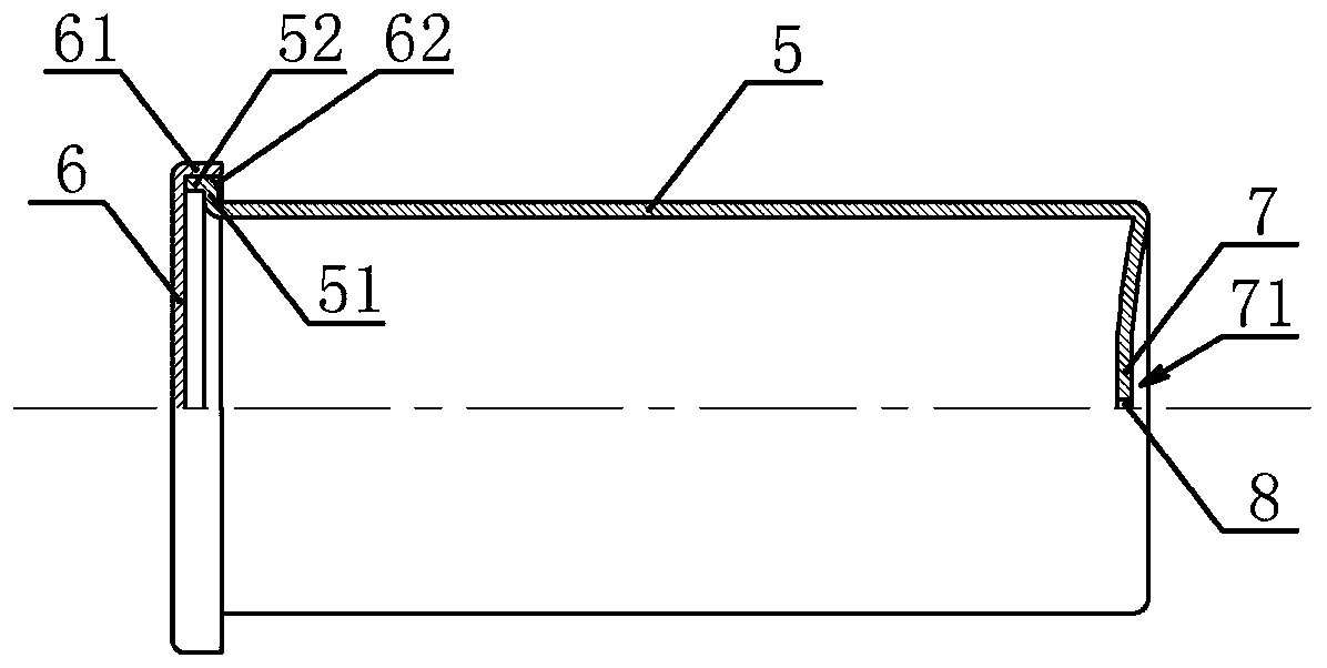
[0021] Such as figure 2 The heat pipe shown includes a tube body 5, and one end of the tube body 5 is connected with a cap 6 for sealing the end of the tube body 5 through a fixed structure. Such as figure 2 As shown, the other end of the tube body 5 has a plugging portion 7 integrally formed with the tube body 5 for plugging the end of the tube body 5, and the middle of the plugging portion 7 has a through hole communicating with the inner cavity of the tube body 5. 8. The plugging part 7 is also provided with a plugging unit for plugging the through hole 8 after the inner cavity of the tube body 5 is evacuated.

[0022] In this embodiment, the plugging portion 7 is formed by rolling of the tube body 5, and the through hole 8 and...


PUM


Abstract

The invention provides a heat pipe, and belongs to the technical field of heat exchange. According to the heat pipe, the problems that an existing heat pipe is unreasonable in structural design, complex in manufacturing process and poor in stability are solved. The heat pipe comprises a pipe body; one end of the pipe body is connected to a sealing cap through a fixing structure, wherein the sealing cap is used for sealing and plugging the end part of the pipe body; the other end of the pipe body is provided with a sealing and plugging part, wherein the sealing and plugging part is integrally formed with the pipe body and is used for sealing and plugging the end part of the pipe body; the middle part of the sealing and plugging part is provided with a through hole, wherein the through holeis in communication with an inner cavity of the pipe body; and the sealing and plugging part is further provided with a sealing and plugging unit, wherein the sealing and plugging unit is used for sealing and plugging the through hole after the inner cavity of the pipe body is vacuumized. The heat pipe has the advantages of being simple in manufacturing process, good in structural stability and the like.

Description

Technical field [0001] The invention belongs to the technical field of heat dissipation and relates to a heat pipe. Background technique [0002] LED lamps generate a lot of heat when they are in use. The heat is first transferred to the aluminum substrate of the LED lamp through the soldering layer, and then transferred to each heat sink through the heat conducting glue of the aluminum substrate, and finally the heat is taken away by the convection between the heat sink and the air. This kind of heat dissipation method is currently the most widely used, with simple design and low cost. Computer servers also use heat pipes to conduct heat to the heat sink to dissipate heat, but the addition of a fan speeds up the air flow on the heat sink surface to take away heat faster and improve the heat dissipation effect. [0003] The structure of the existing heat pipe is figure 1 As shown, the main pipe 2 is included. One end of the main pipe 2 is provided with a cap 1 and the other end is...

Claims


Application Information

Patent Timeline
Patent Type & Authority Applications(China)
IPC IPC(8): F28D15/02
Inventor 陈雪芬
Owner 温岭市雪鹏机械有限公司
Learn More