
Drill rod welding robot production line

A welding robot and production line technology, applied in welding equipment, auxiliary welding equipment, welding/cutting auxiliary equipment, etc., can solve problems such as smoke, low degree of automation, and inability to quickly change models, so as to reduce self-weight deformation and downward deformation , Improve the degree of automation, improve the effect of production efficiency

Active Publication Date: 2019-06-25
成都焊研威达科技股份有限公司
View PDF11 Cites 6 Cited by
  • Summary
  • Abstract
  • Description
  • Claims
  • Application Information

AI Technical Summary

Problems solved by technology

[0003] The purpose of the present invention is to provide a drill pipe welding robot production line, which is used to solve the problems of low automation and inability to quickly change the type of the drill pipe welding production line in the prior art, as well as the smoke and dust problem caused by the electric welding environment in the prior art

Method used


Image

  • Drill rod welding robot production line
  • Drill rod welding robot production line
  • Drill rod welding robot production line

Examples


Embodiment 1

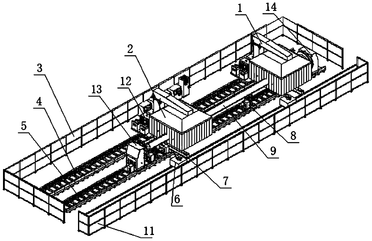
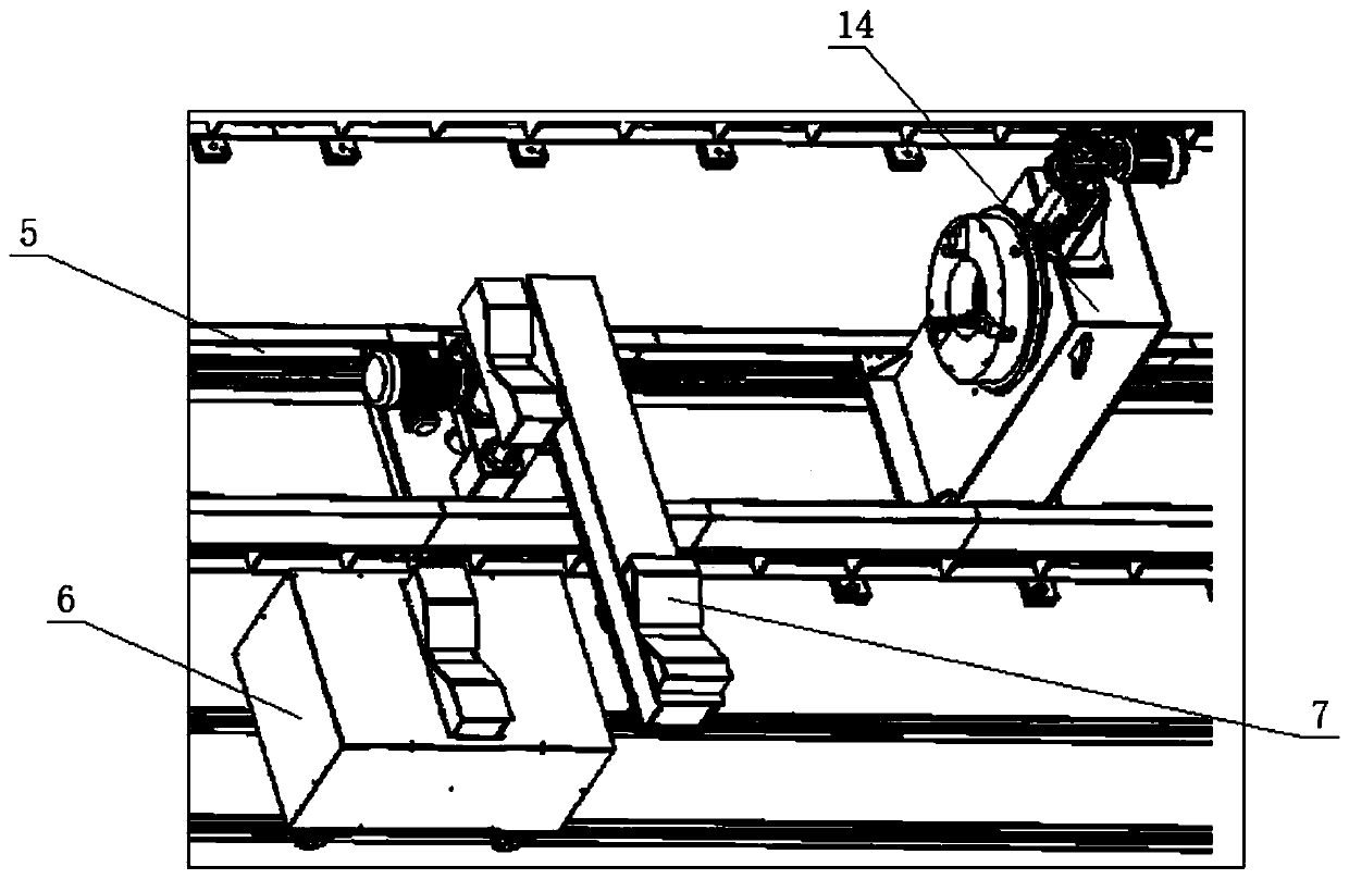
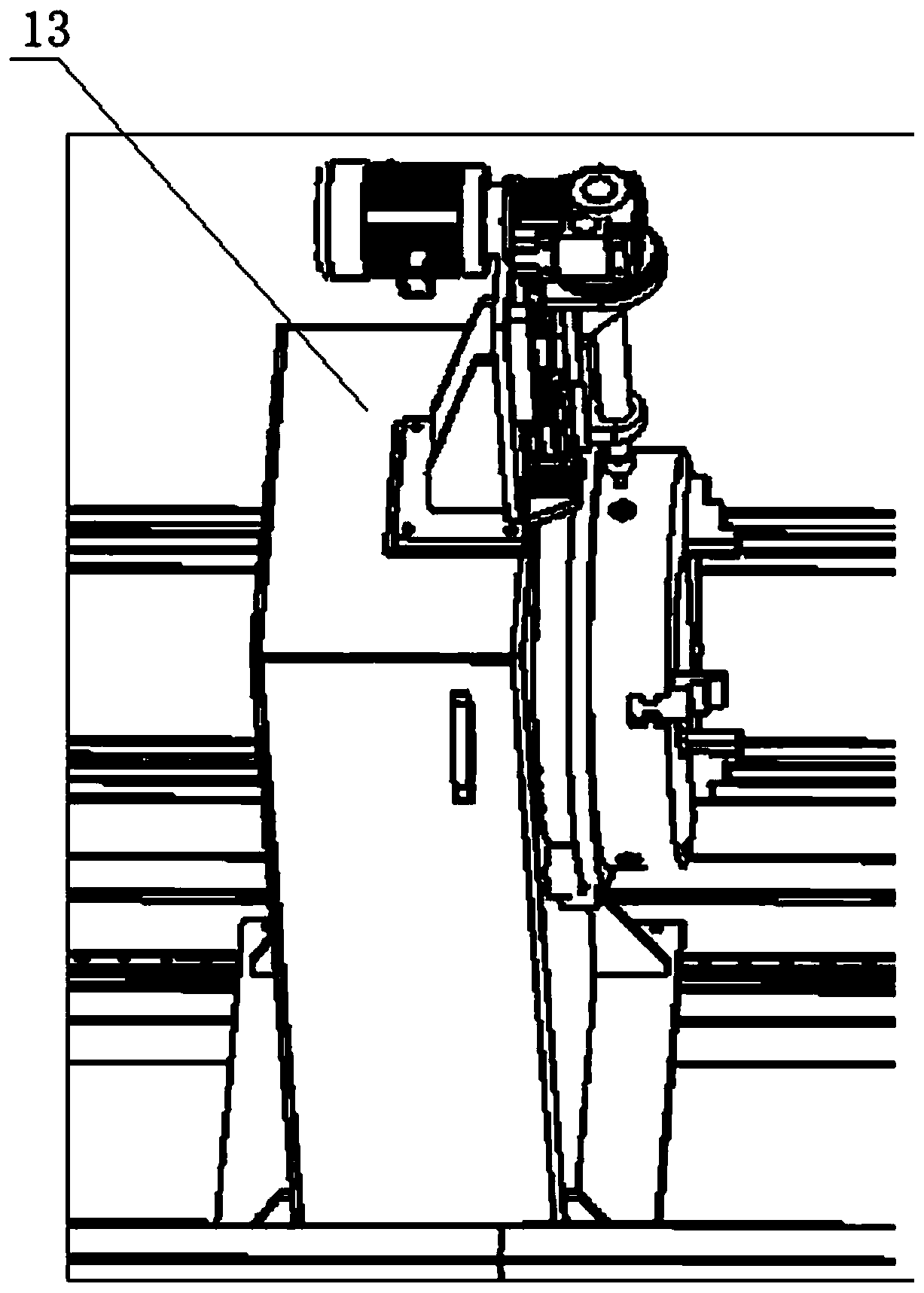
[0038] combined with Figure 1-3Shown, a kind of drill pipe welding robot production line, comprises power source and water tank 12, also comprises positioner moving track 5 and the positioner installed on positioner moving track 5, one of described positioner moving track 5 A robot moving track 4 is arranged in parallel on the side, and an inverted "L"-shaped cantilever 1 is slidably installed on the robot moving track 4. The cantilever 1 includes columns and beams at right angles to each other, and a robot is hung upside down on the beam. , the other side of the moving track 5 of the positioner is provided with two or more mobile trolleys 6, the positioner includes a positioner headstock 13 and a positioner tailstock 14, the positioner head Seat 13, positioner tailstock 14 are all provided with electric chuck, and described positioner headstock 13, positioner tailstock 14 are respectively connected drive unit, and described drive unit is used for driving positioner headstock...

Embodiment 2

[0042] On the basis of embodiment 1, it also includes a hood-type soot purification device 2, which includes a soot purifier, a soot purification pipeline, a soot net cover and a flexible plastic curtain, and the soot purification pipeline is fixed on the On the above-mentioned cantilever 1, one end of the soot purification pipe is connected to the air outlet of the soot purifier, and the other end of the soot purification pipe is connected through the soot net cover, and a fixing groove is opened around the soot net cover, and the fixation groove A plastic curtain is fixed inside, and the top of the smoke and dust net cover is provided with a through hole for the robot to seal and penetrate.

[0043] When the robot is welding, it is completely in the space surrounded by the fume hood and the plastic curtain. The fume generated by welding can be discharged through the fume purification pipe connected with the fume hood, and purified by the fume purifier to avoid polluting the e...

Embodiment 3

[0046] On the basis of Example 1, in conjunction with the attached Figure 4 and Figure 5 As shown, the auxiliary supporting device 8 includes a lifting mechanism and a traversing mechanism, and the lifting mechanism includes a fixed base 84 on which a lifting motor 81 and a lifting screw 82 are installed. The motor 81 is drivingly connected with the lifting screw 82, the lifting block 83 for supporting the workpiece is installed on the top of the lifting screw 82, and the traversing mechanism includes a traversing motor 87 and is used for installing the fixed seat 84 and The base 85 of the traverse motor 87 is provided with a gear 86 at the bottom end of the base 85, and the gear 86 is driven by the traverse motor 87. The base 85 is provided with guide columns 88 on both sides of the lifting screw 82.

[0047] Further, the lifting block 83 is a cuboid or a cuboid with a V-shaped groove or an inverted trapezoidal groove at its upper end.

[0048] Multiple auxiliary support ...


PUM


Abstract

The invention discloses a drill rod welding robot production line comprising a positioner movement rail, a positioner and a robot movement rail. Cantilevers are installed on the robot movement rail. Robots are arranged on the cantilevers in an upside-down hanging manner. The drill rod welding robot production line further comprises movement trolleys, material receiving and sending devices and an auxiliary supporting device. The movable positioner comprises a positioner head base and a positioner tail base. The invention further discloses an automatic welding method. The automatic welding method includes the steps that the movement trolleys convey a drill rod workpiece to the material receiving and sending devices, and the material receiving and sending devices place the drill rod workpieceon an auxiliary supporting part; the auxiliary supporting part automatically regulates the height, and therefore the drill rod workpiece can be fixed through electric chucks conveniently; the robotsautomatically complete the welding work; and the auxiliary supporting part places the drill rod workpiece on the upper faces of the material receiving and sending devices, the drill rod workpiece is conveyed away through the movement trolleys, and discharging is completed. The robots in the drill rod welding robot production line can weld different positions of the same workpiece at the same time,the production efficiency is greatly improved, and rapid type change of the workpiece can be achieved; and automatic material receiving and sending are completed, the previous working procedure and the next working procedure are connected, and the automation degree is improved.

Description

technical field [0001] The invention relates to the technical field of welding and automatic control, in particular, it relates to a drilling pipe welding robot production line. Background technique [0002] The production process of drill pipes is produced in a complete set, and there may be different workpieces in each production cycle, so it is required that the equipment can be quickly changed. Among them, due to the low degree of automation in the existing technology, manual loading and unloading is required, which not only increases The labor intensity of the workers is increased, the assembly accuracy of the workpiece cannot be guaranteed, and the improvement of production efficiency is limited at the same time. At the same time, due to the smoke and dust brought by the electric welding environment, the environment is polluted. Contents of the invention [0003] The purpose of the present invention is to provide a drill pipe welding robot production line, which is ...

Claims


Application Information

Patent Timeline
Patent Type & Authority Applications(China)
IPC IPC(8): B23K37/00
Inventor 陈本亮温元德贾宏宇王锦夏
Owner 成都焊研威达科技股份有限公司
Learn More