
Bisconical microchannel radiator with thermosyphon loop

A technology of micro-channels and heat sinks, applied in the field of heat pipes, can solve the problems of hindering the heat exchange of the refrigerator gas, the length of the micro-channel flow channel is too long, and the heat exchange efficiency is reduced, so as to increase the effective heat exchange area and maintain the wet characteristics , the effect of strong heat transfer performance

Pending Publication Date: 2019-06-18
NANCHANG UNIV
View PDF0 Cites 6 Cited by
  • Summary
  • Abstract
  • Description
  • Claims
  • Application Information

AI Technical Summary

Problems solved by technology

In this process, when the filling rate of the refrigerant in the tube is large, the heat transfer area is small because the heat transfer part is only limited to the periphery of the evaporation end and the bottom wall. If the temperature is low, it will cool down the heated and evaporated refrigerant gas and cause partial liquefaction, which will prevent the gas from rising to the condensation end for heat exchange, and further reduce the heat exchange efficiency, which cannot meet the heat dissipation of the current highly integrated microelectronic chips. A heat dissipation device capable of meeting the rapidly increasing heat flux density of microelectronics, a double-tapered microchannel heat sink with thermosiphon can play its characteristics in this case
Most of the existing radiators use standard circular or rectangular thermosiphons, which have a small heat transfer area, and the heat transfer is easy to deteriorate in the case of high filling rates; while the existing microchannel radiators generally have microchannel flow channels. If the length is too long, the pressure drop is large, and the fluid distribution is uneven, and the internal space of the microchannel is narrow, the expansion of the refrigerant that absorbs heat and vaporizes will hinder the subsequent refrigerant liquid, affecting fluid circulation and reducing heat transfer efficiency

Method used


Image

  • Bisconical microchannel radiator with thermosyphon loop
  • Bisconical microchannel radiator with thermosyphon loop
  • Bisconical microchannel radiator with thermosyphon loop

Examples


Embodiment Construction

[0021] The present invention will be further explained below in conjunction with the drawings and embodiments:

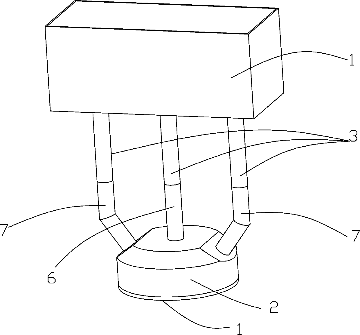
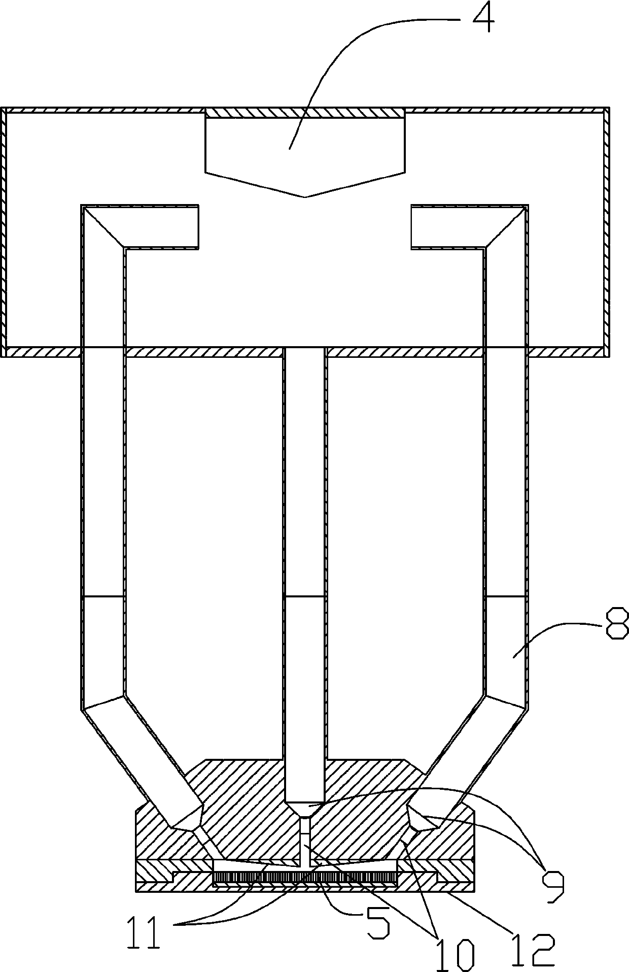
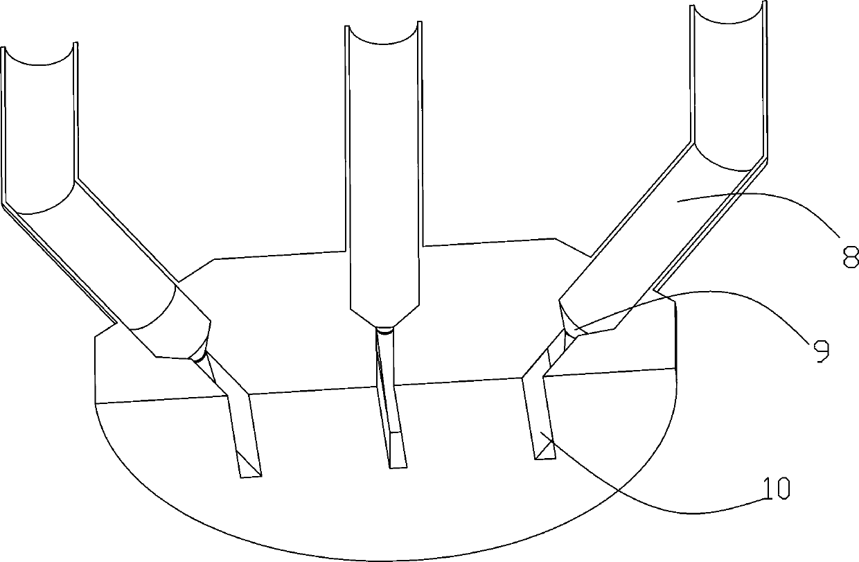
[0022] See Figure 1-5 .

[0023] The invention discloses a double-taper microchannel radiator with a thermosiphon circuit, which comprises a condensation end, an evaporation end, and a refrigerant delivery pipe 3 communicating with the condensation end and the evaporation end. The condensation end is a cooling water tank 1, and the cooling A micro-channel condenser 4 is arranged in the cavity of the water tank 1; the evaporating end is a heat absorption box 2, and the heat absorption box 2 is a cavity structure provided with a cavity inside, and the cavity of the heat absorption box 2 is arranged There is a micro-channel radiator 5, the top of the micro-channel radiator 5 is provided with a refrigerant outlet hole 7 and a refrigerant inlet hole 6 passing through the top of the heat absorption box 2. The refrigerant outlet hole 7 and the refrigerant inlet hole 6 are bot...


PUM


Abstract

The invention relates to the technical field of heat pipes, in particular to a bisconical microchannel radiator with a thermosyphon loop. The bisconical microchannel radiator comprises a condensationend, an evaporation end and a refrigerant delivery pipe; the refrigerant delivery pipe is used for communicating the condensation end with the evaporation end; the condensation end is provided with acooling water tank; a microchannel condenser is arranged in a cavity of the cooling water tank; a heat-absorbing box is arranged at the evaporation end; the heat-absorbing box is of a cavity structure; a cavity is formed in the cavity structure; the microchannel radiator is arranged in the cavity of the heat-absorbing box; and a refrigerant outlet and a refrigerant inlet which penetrate through the top end of the heat-absorbing box are formed in the microchannel radiator. With negative pressure generated after refrigerant gas is condensed and gravity on condensed refrigerant liquid as circulating power, energy can be saved when the designed radiator obtains high heat exchange performance.

Description

Technical field [0001] The invention relates to the technical field of heat pipes, in particular to a double-taper microchannel radiator with a thermosiphon circuit. Background technique [0002] Microfluidic heat dissipation technology is an emerging embedded chip-level enhanced cooling technology. It directly cools the chip through a micro-scale continuous fluid, which minimizes the influence of the thermal resistance between the heat sinks in the remote heat dissipation mode on the heat dissipation efficiency, thereby greatly improving the cooling efficiency of the heat sink. The micro-channel heat sink uses micro-channels to divide the cooling fluid into tiny fluids, and each fluid combination cools the components required to dissipate heat. [0003] The thermal resistance between the microchannel heat exchanger and the heat exchange environment is extremely low, and it has a very high heat exchange efficiency. The separated fluids exchange heat on different microchannel flow ...

Claims


Application Information

Patent Timeline
IPC IPC(8): F28D15/02
Inventor 张莹张道旭高辉李培生李文彬雷杰陈岳姚孟君彭澄宇连小龙刘强
Owner NANCHANG UNIV
Learn More