
A pressure dividing device for pneumatic vehicles

A technology for pneumatic vehicles and equipment, applied in the directions of brakes, vehicle components, brake transmissions, etc., can solve the problems of difficult coordination, high risk, and low reliability in the coordination of vehicle driving and braking. Maneuverability, low cost, effect of ensuring stability and safety

Active Publication Date: 2020-04-21
桂林逸成智能装备有限公司
View PDF5 Cites 0 Cited by
  • Summary
  • Abstract
  • Description
  • Claims
  • Application Information

AI Technical Summary

Problems solved by technology

[0003] The current pressure dividing equipment is generally completed by air pressure valve or air valve, pressure valve, because the air valve not only has a short lifespan for high-pressure air flow, but also has low reliability. , the method of relying only on the air valve is more dangerous, and it is difficult to ensure the coordination of the driving and braking of the car

Method used


Image

  • A pressure dividing device for pneumatic vehicles
  • A pressure dividing device for pneumatic vehicles
  • A pressure dividing device for pneumatic vehicles

Examples


Embodiment Construction

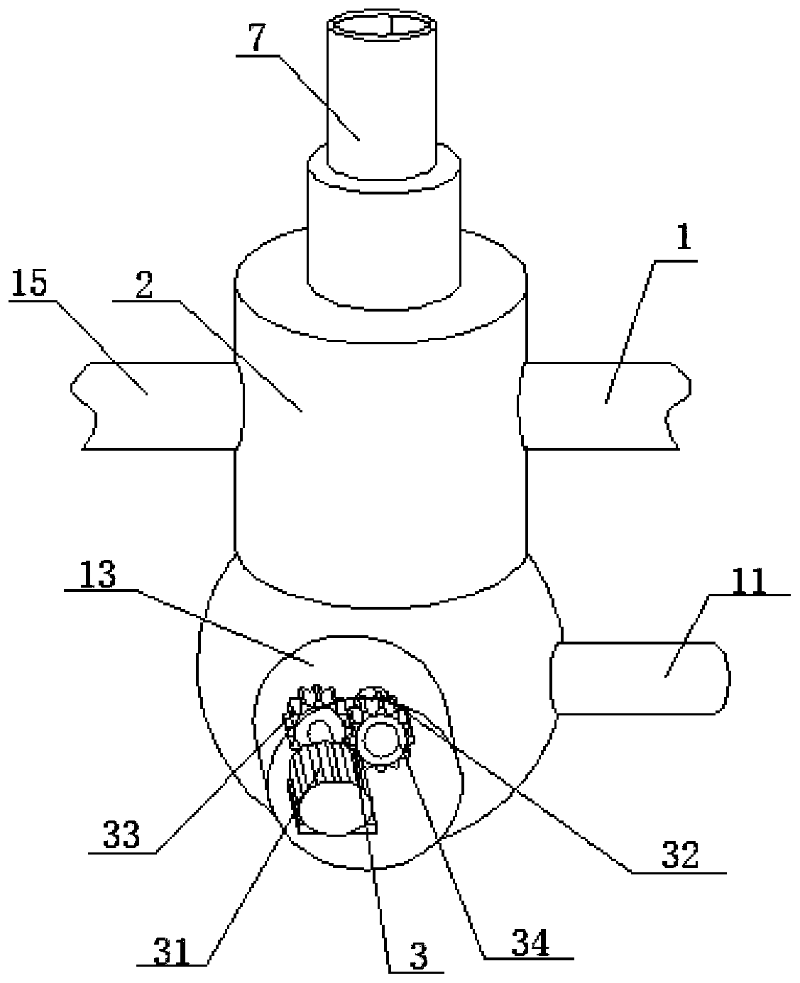
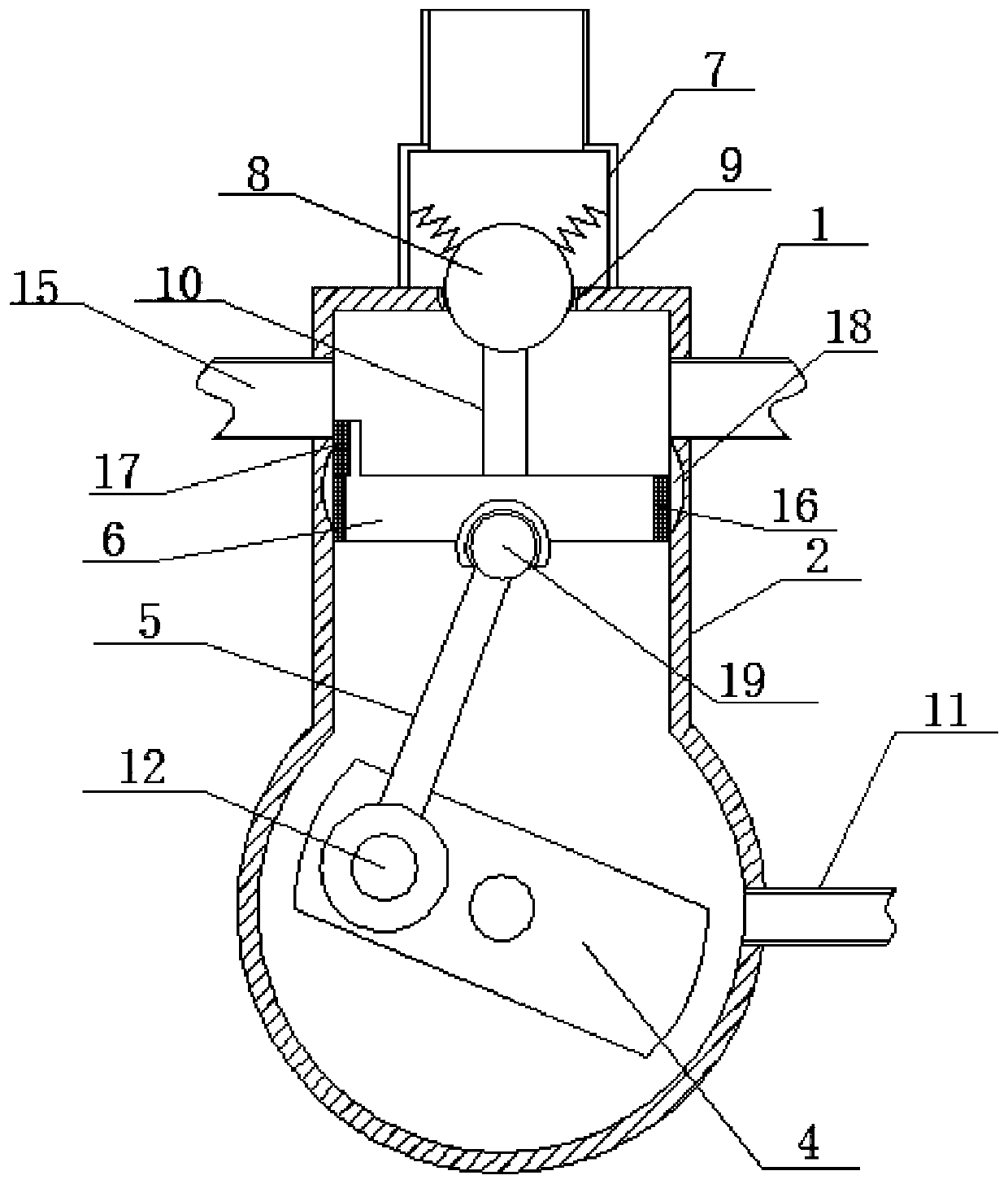
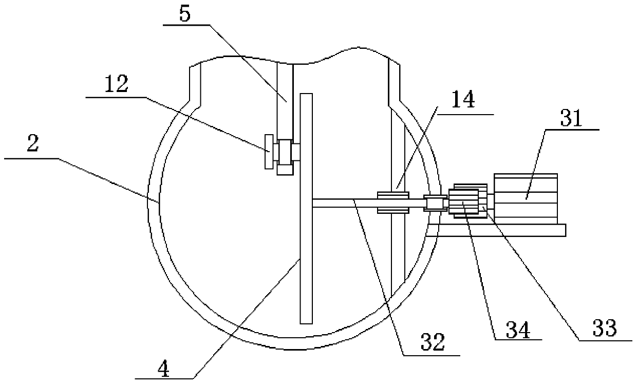
[0027] see Figure 1~3 , in the embodiment of the present invention, a kind of pressure-dividing equipment for pneumatic vehicle, comprises air intake pipe 1, pressure-dividing tank 2, driving air pipe 15, rear brake pipe 7 and front brake pipe 11, it is characterized in that the pressure-dividing The box 2 is provided with a manipulation assembly, one side of the pressure dividing box 2 is provided with the air inlet pipe 1, and the other side of the pressure dividing box 2 is provided with a driving air pipe 15 arranged opposite to the air inlet pipe 1, The driving air pipe 15 communicates with the vehicle power drive mechanism;

[0028] A front brake pipe 11 is communicated with the side of the control assembly on the pressure divider box 2, and the front brake pipe 11 communicates with the braking mechanism of the front wheel of the automobile;

[0029] A rear brake pipe 7 is connected to the side of the pressure divider box 2 away from the steering assembly, and the rear...


PUM


Abstract

The invention discloses a pressure separating device for a pneumatic vehicle. By designing the structure, the driving air pressure and braking air pressure of the air pressure can be separated throughthe structure of a pressure separating box, and it can be ensured that rear wheels of the vehicle are braked, then front wheels of the vehicle are braked and the time difference between the rear wheels and the front wheels is realized and the vehicle braking stability and safety can be ensured during braking. Through the structural design of the pressure separating box, the pressure separating reliability can be effectively ensured, and the problem that an electromagnetic valve is high in bearing capacity, prone to damage and not high in reliability when control is conducted completely through the electromagnetic valve is reduced; the pressure separating device is reasonable in structure, simple in driving device structure, convenient to manufacture, low in cost and long in service life,the delay time between the air flow flowing to a front brake pipe and the air flow flowing to a rear brake pipe is realized by adjusting the relative positions of a pressure relief groove, a piston and a spherical end cap and the movement speed of the piston, and the vehicle braking and driving stability is ensured.

Description

technical field [0001] The invention relates to the technical field of pneumatic vehicles, in particular to a pressure dividing device for pneumatic vehicles. Background technique [0002] Due to the rising cost of petroleum fuel vehicles, "green design" has become the design concept of new vehicles, so people pay more and more attention to pneumatic vehicles. Among them, the pneumatic vehicle uses high-pressure air to drive the air motor. Therefore, in view of the green and environmental performance of the pneumatic vehicle, its development prospect is very considerable. However, for pneumatic vehicles, since the main power such as its power and braking needs to come from air pressure, the pressure dividing device of air pressure is very important. [0003] The current pressure dividing equipment is generally completed by air pressure valve or air valve, pressure valve, because the air valve not only has a short lifespan for high-pressure air flow, but also has low reliabi...

Claims


Application Information

Patent Timeline
Patent Type & Authority Patents(China)
IPC IPC(8): B60T13/26B60T17/04
Inventor 赵宏旺黄兴华李岚琦刘宇腾刘腾远
Owner 桂林逸成智能装备有限公司
Learn More