
Water-cooled self-tempering process and device of steel pipe

A technology of self-tempering and water spraying devices, which is applied in the direction of manufacturing tools, furnaces, heat treatment equipment, etc., can solve the problems that the structure and mechanical properties cannot meet the needs of non-high-pressure boiler steel pipe customers, do not meet the tensile strength, and the cooling time is long. To achieve the effect of effective control of cooling speed, performance improvement and strength improvement

Active Publication Date: 2019-06-11
ZHEJIANG MINGHE STEEL PIPE CO LTD
View PDF2 Cites 6 Cited by
  • Summary
  • Abstract
  • Description
  • Claims
  • Application Information

AI Technical Summary

Problems solved by technology

[0006] The steel pipe water mist cooling method disclosed in this patent is suitable for cooling high-pressure boiler pipes. High-pressure boiler pipes refer to seamless steel pipes that meet the Chinese national standard GB / T5310-2008. The yield strength of high-pressure boiler pipes obtained by heat treatment according to this method is 330-350MPa , does not meet the requirements of non-high-pressure boiler steel pipe customers for low-carbon manganese steel pipes with a tensile strength of 700MPa, a yield strength of 500MPa, and an impact of more than 50J. It is ferrite + pearlite + bainite, or precipitated martensite, whose microstructure and mechanical properties cannot meet the needs of non-high-pressure boiler steel pipe customers

Method used


Image

  • Water-cooled self-tempering process and device of steel pipe
  • Water-cooled self-tempering process and device of steel pipe
  • Water-cooled self-tempering process and device of steel pipe

Examples


Embodiment Construction

[0043] The technical solutions of the present invention will be further described below in conjunction with the accompanying drawings and through specific implementation methods.

[0044] Wherein, the accompanying drawings are only for illustrative purposes, showing only schematic diagrams, rather than physical drawings, and should not be construed as limitations on this patent; in order to better illustrate the embodiments of the present invention, some parts of the accompanying drawings will be omitted, Enlargement or reduction does not represent the size of the actual product; for those skilled in the art, it is understandable that certain known structures and their descriptions in the drawings may be omitted.

[0045] In the drawings of the embodiments of the present invention, the same or similar symbols correspond to the same or similar components; , "inner", "outer" and other indicated orientations or positional relationships are based on the orientations or positional ...


PUM

PropertyMeasurementUnit
thicknessaaaaaaaaaa
yield strengthaaaaaaaaaa
tensile strengthaaaaaaaaaa

Abstract

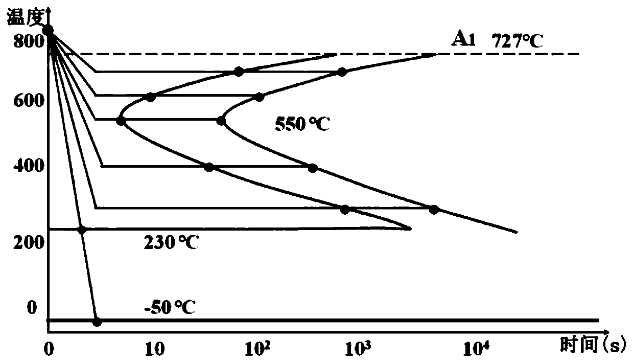
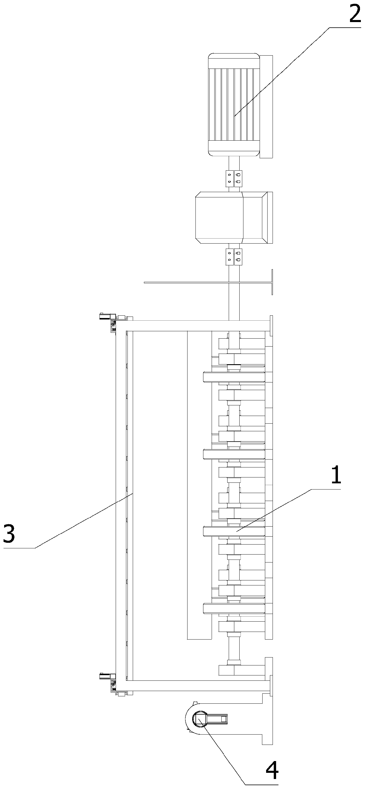
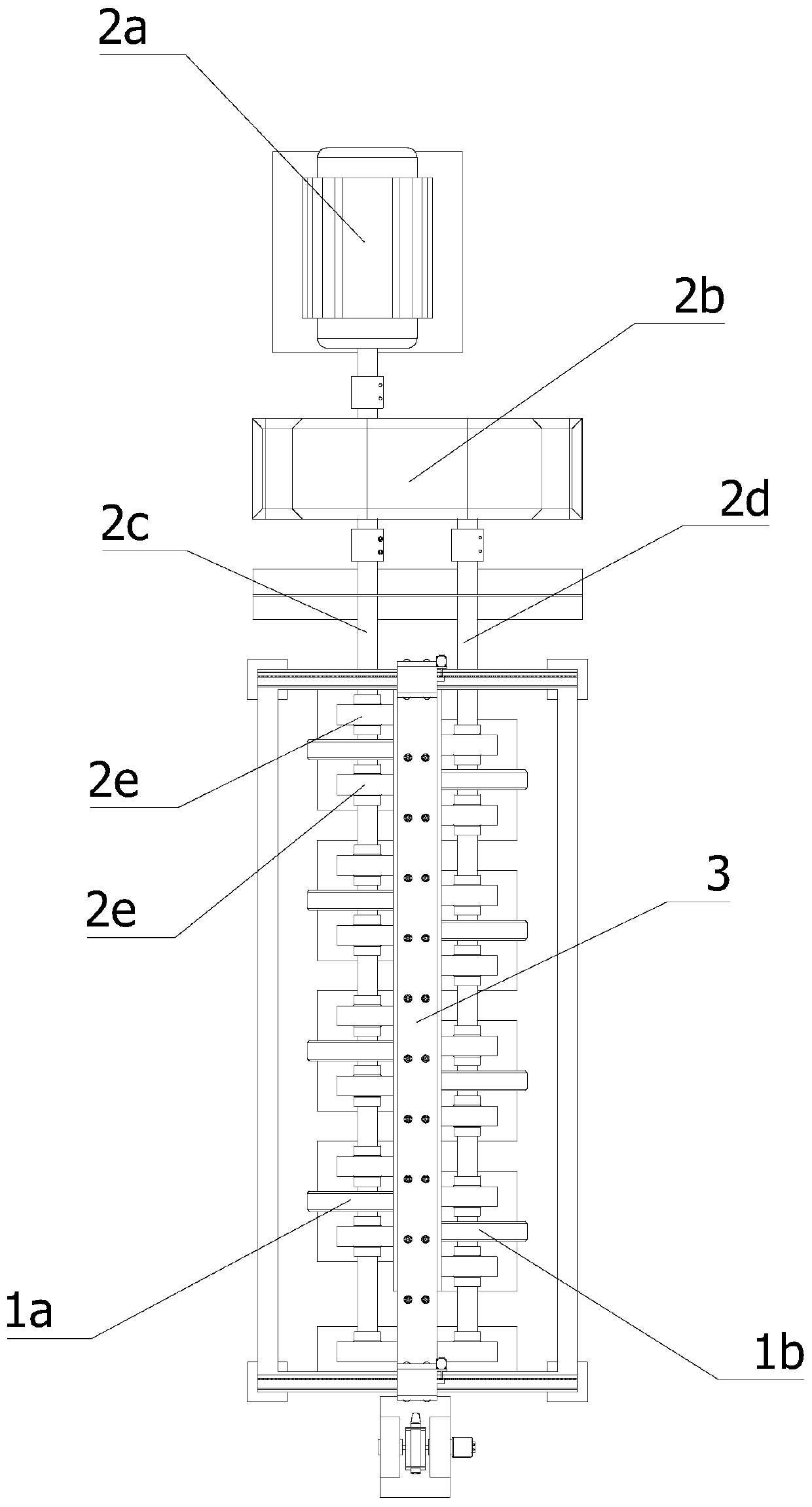
The invention relates to a water-cooled self-tempering process of a steel pipe. The process includes the following steps of S1, high-temperature slow cooling, wherein the completely austenitized steelpipe is transferred to a supporting wheel set, the supporting wheel set drives the steel pipe to rotate, the steel pipe is air-cooled to 50-100 DEG C below the holding temperature, and the air cooling time is 10-50 s; S2, middle-temperature water rapid cooling, wherein the steel pipe is simultaneously cooled through a steel pipe outer wall water spraying device and a steel pipe inner wall water spraying device, and the steel pipe is cooled to 550-650 DEG C within 5-20 s; and S3, low-temperature cooling, wherein the steel pipe is slowly cooled to room temperature, and self-tempering treatmentis carried out. The invention further discloses a device for the process. The process and the device have the beneficial effects that the steel pipe is rapidly cooled to 550-650 DEG C, fine pearlite can be obtained when the steel pipe is slowly cooled, the strength of the steel pipe is improved, the impact toughness of materials is stabilized, the tensile strength of the materials can reach about700 Mpa, the yield strength can reach 500 Mpa or above, the impact reaches 50 J or above, other performance can meet the high requirements of users, and energy saving and environmental protection areachieved.

Description

technical field [0001] The invention relates to the technical field of heat treatment of ordinary low-carbon Mn steel and steel pipes with a wall thickness of more than 30 mm, in particular to a water-cooled self-tempering process and device for steel pipes. Background technique [0002] Ordinary low-carbon steel pipe is Mn steel and the wall thickness of the steel pipe is above 30mm. As customers have higher and higher requirements for product performance, the ordinary 20MnV6 wall thickness is ≥30mm, the tensile requirement is ≥630Mpa, and the yield requirement is ≥450Mpa. -20°C impact ≥ 27J, the traditional normalizing process cannot meet customer requirements, and most of them use quenching + tempering at this stage to meet customer requirements. [0003] At this stage, after the steel pipe is quenched and tempered, due to the huge difference in the cooling rate between the inner and outer surfaces of the steel pipe and its core, the cross-sectional structure and properti...

Claims


Application Information

Patent Timeline
Patent Type & Authority Applications(China)
IPC IPC(8): C21D9/08
Inventor 汤小秒孙焕军赵小龙陶宏宇
Owner ZHEJIANG MINGHE STEEL PIPE CO LTD
Learn More