
Power thermal switching method and system for power grid, electronic equipment and computer readable medium

A technology of hot switching and power supply, which is applied in the direction of emergency power supply arrangement, electrical components, circuit devices, etc., can solve the problems of large nuclear phase workload, hidden safety hazards and hidden dangers of overheating, and achieve the effect of high-efficiency continuous use

Pending Publication Date: 2019-06-07
STATE GRID ZHEJIANG CIXI POWER SUPPLY +2
View PDF8 Cites 0 Cited by
  • Summary
  • Abstract
  • Description
  • Claims
  • Application Information

AI Technical Summary

Problems solved by technology

In actual operation, the first step is easy to grasp. After the power flow calculation, almost all operating modes can be closed. Therefore, as long as the first calculation is correct, there will be no danger in the future, but for the second step, there is Larger hidden danger
This is because the transformation of the distribution network is more frequent, there are many contact points of the line, and the extensive use of cables makes the phase of the contact point may change after the line is changed. Therefore, the phase verification should be performed again after each line transformation. , which makes the phase verification workload very large. Moreover, if the line construction unit fails to contact the operation department in time, there may be an event that the phase is not re-verified after the line change, thus leaving a safety hazard for the heat sink

Method used


Image

  • Power thermal switching method and system for power grid, electronic equipment and computer readable medium
  • Power thermal switching method and system for power grid, electronic equipment and computer readable medium
  • Power thermal switching method and system for power grid, electronic equipment and computer readable medium

Examples


Embodiment Construction

[0026] Example embodiments will now be described more fully with reference to the accompanying drawings. .

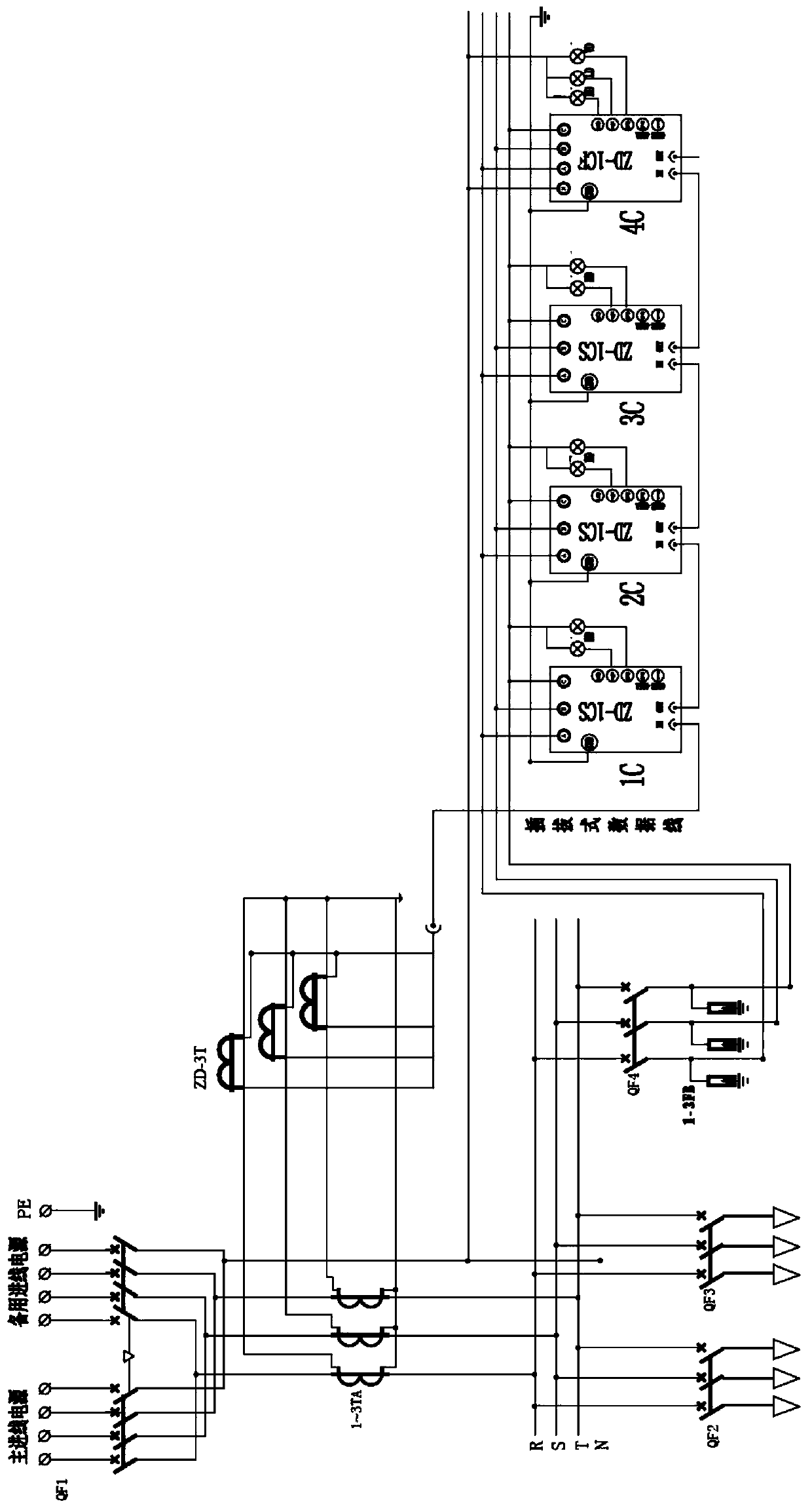
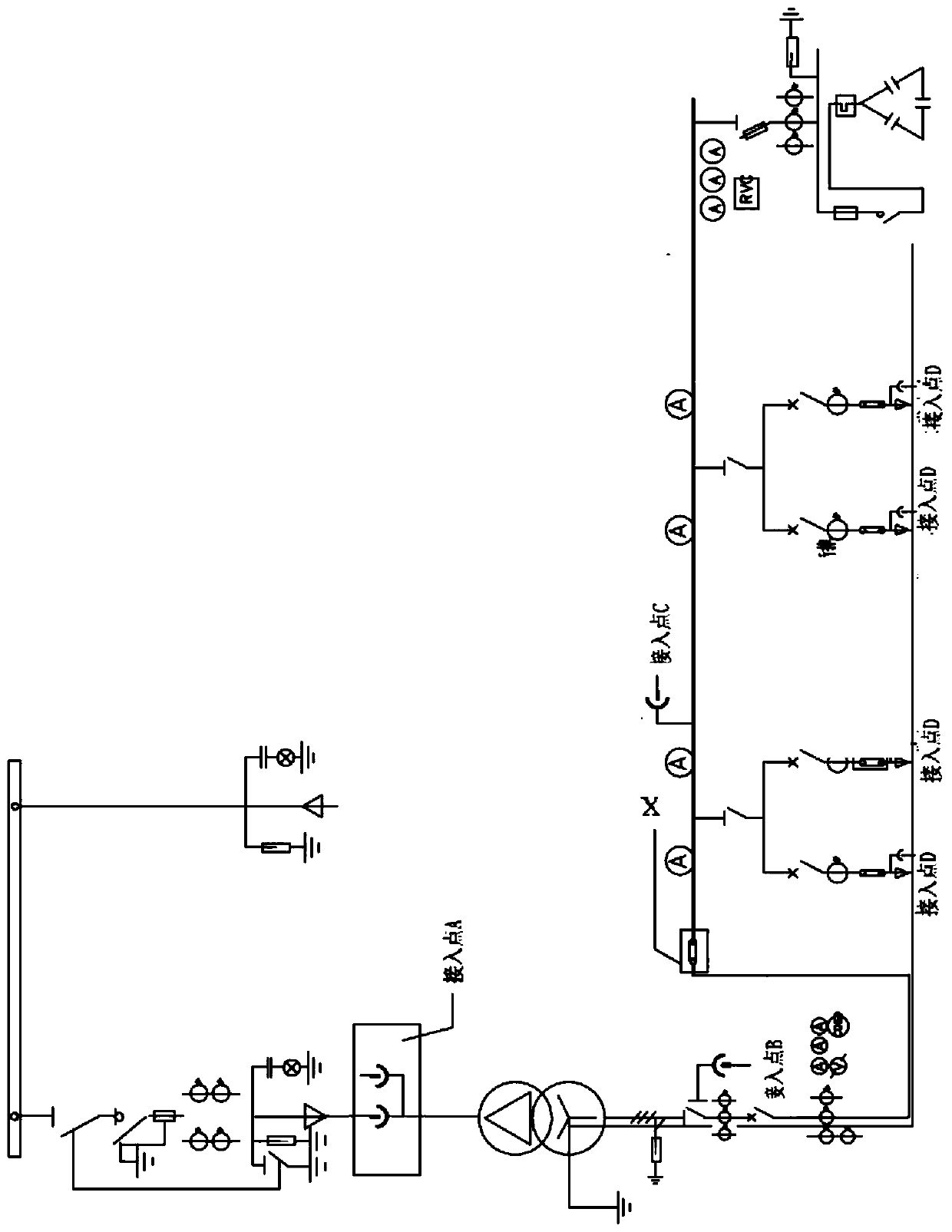
[0027] figure 1 It is a system functional block diagram of a power monitoring system for a power grid according to an exemplary embodiment. figure 1 An exemplary schematic diagram of a power conversion system with 2 input power sources to be converted is described. It is not general, and a schematic diagram of a power conversion system with more power sources to be converted will be easily obtained by figure 1 Deduced.

[0028] like figure 1 As shown, the power conversion system for the grid with 2 input power sources may include the main incoming power supply and the backup incoming power supply. In other embodiments, the power conversion system for the grid with multiple input power sources may include the first The first incoming power supply, the second incoming line power supply, the third incoming line power supply, etc., all the above incoming line power supp...


PUM


Abstract

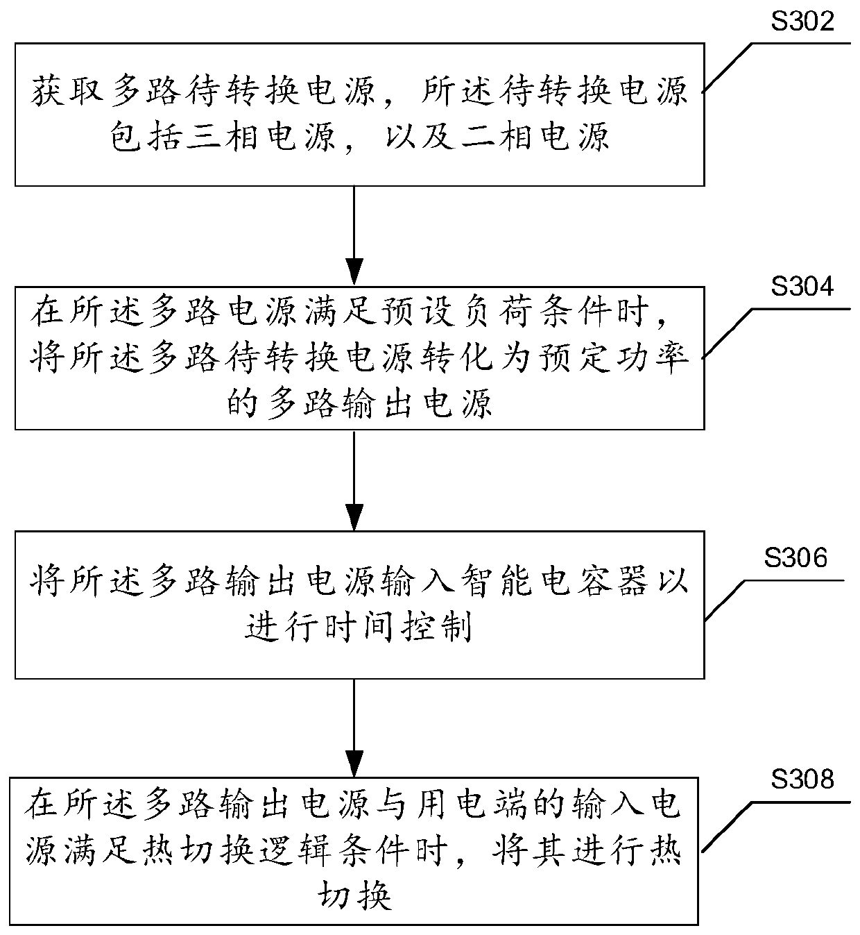
The invention discloses a power thermal switching method and system for a power grid, electronic equipment and a computer readable medium. The method comprises the following steps: obtaining multipleto-be-converted power supplies, wherein the to-be-converted power supplies comprise a three-phase power supply and a two-phase power supply; when multiple to-be-converted power supplies meet a presetload condition, converting multiple to-be-converted power supplies into multiple output power supplies with preset power; inputting multiple output power supplies into an intelligent capacitor for time control; and when multiple output power supplies and the input power supply of a power utilization end meet a thermal switching logic condition, carrying out thermal switching on multiple output power supplies and the input power supply. According to the invention, the method and system achieve the quick switching of a user to other power supplies in the processes of replacing, overhauling and the like of comprehensive electricity, and achieve the purpose of continuously using the power supplies of the user safely and efficiently.

Description

technical field [0001] The present disclosure relates to the technical field of power electronics. Background technique [0002] Generally, in the power supply system, according to the reliability of the power supply requirements, a dual-circuit power supply will be used for power supply. When one power supply fails, it will be required to switch the load on one line to another line. This is the so-called load reversal. , When the load is reversed, because the two-circuit power supply needs to be closed instantly, the current of the closed loop is relatively large, so when the load is reversed in a short time, depending on the specific situation, there may be a situation of power failure and load reverse. Reverse load: refers to the operation of transferring the load of a line (or transformer) to other lines (or transformers) for power supply. Cold down: When a line needs to borrow power, first cut off the power of the line, and then close the contact switch between the two...

Claims


Application Information

Patent Timeline
Patent Type & Authority Applications(China)
IPC IPC(8): H02J9/06
Inventor 应永灵童灵华马振宇苏毅芳朱圣盼叶浓美袁志波王林杰王坚沈旭
Owner STATE GRID ZHEJIANG CIXI POWER SUPPLY
Learn More