Conductive control device of fiber brush structure

A technology of control devices and fiber brushes, applied in the direction of circuits, current collectors, electrical components, etc., can solve the problems of single copper wire wear, short service life, large contact wear, etc., achieve low contact wear rate, no lubricant, contact low pressure effect

Pending Publication Date: 2019-06-07
丹阳市长江汽车部件有限公司
View PDF8 Cites 0 Cited by
  • Summary
  • Abstract
  • Description
  • Claims
  • Application Information

AI Technical Summary

Problems solved by technology

[0002] The conductive control device is used for signal transmission of large-scale mechanical equipment such as heavy machinery and equipment. The single copper wire brush commonly used inside the existing various types of conductive control devices has a gap between the single copper wire of the copper wire brush and the conductive ring. The contact point, under the surrounding conditions, the contact pressure is large, the contact wear is large, and the service life is short; in addition, the single copper wire will be worn after a long time of use, and the copper wire will loosen, resulting in poor contact.

Method used


Image

  • Conductive control device of fiber brush structure
  • Conductive control device of fiber brush structure
  • Conductive control device of fiber brush structure

Examples


Embodiment Construction

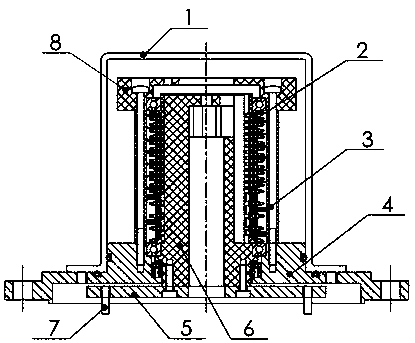
[0018] Depend on figure 1 It is known that a conductive control device with a fiber brush structure includes a central slip ring assembly 2, a base 4, a transmission disc 5, a support disc 6 and a transmission pin 7, and a circular boss is arranged in the middle of the base 4, and the circular A matching hole is provided in the middle of the boss; the central slip ring assembly 2 is fixed on the support disc 6, and the bottom end of the support disc 6 is fixed on the transmission disc 5 through the cooperation hole in the middle of the base 4, and the transmission disc 5 is also provided below There is a transmission pin shaft 7 that is threaded; it is characterized in that: the conductive control device also includes a fiber brush assembly 3, and the fiber brush assembly 3 is fixed on the circular boss of the base 4 by bolts, and the transmission pin shaft 7 will The power on the connecting device is transmitted to the transmission disc 5 to drive the central slip ring assemb...


PUM


Abstract

The invention discloses a conductive control device of a fiber brush structure, and the device comprises a central slip ring assembly (2), a base (4), a transmission disc (5), a supporting disc (6) and a transmission pin shaft (7). A circular boss is arranged at the middle of the base (4), and a matching hole is formed at the middle of the circular boss. The central slip ring assembly (2) is fixedon the supporting disc (6), and the bottom end of the supporting disc (6) is fixed on the transmission disc (5) through a matching hole at the middle of the base (4). The transmission pin shaft (7) in threaded connection is further arranged below the transmission disc (5). The device is characterized in that the electric conduction control device further comprises a fiber brush assembly (3); thefiber brush assembly (3) is fixed to the circular boss of the base (4) through a bolt, and the transmission pin shaft (7) transmits power on a later-stage connecting device to the transmission disc (5) to drive the center sliding ring assembly (2) to rotate together, so that the center sliding ring assembly (2) and the fiber brush assembly (3) move relatively. The device is convenient to use.

Description

technical field [0001] The invention relates to engineering hoisting machinery and drilling machinery, in particular to a conductive control device with a fiber brush structure. Background technique [0002] The conductive control device is used for signal transmission of large-scale mechanical equipment such as heavy machinery and equipment. The single copper wire brush commonly used inside the existing various types of conductive control devices has a gap between the single copper wire of the copper wire brush and the conductive ring. At the contact point, under the condition of surrounding, the contact pressure is large, the contact wear is large, and the service life is short; in addition, the single copper wire will wear out after a long time of use, and the copper wire will loosen, resulting in poor contact. Contents of the invention [0003] In view of the above shortcomings, the purpose of the present invention is to provide a conductive control device with a fiber...

Claims


Application Information

Patent Timeline
Patent Type & Authority Applications(China)
IPC IPC(8): H01R39/18H01R39/24H01R39/39
Inventor 聂顺康陆宇锋
Owner 丹阳市长江汽车部件有限公司
Why Eureka
Try Eureka