Multi-channel high-flux composite ionization device
A high-throughput, multi-channel technology, applied in the field of ionization, can solve the problems of less channels, low ionization efficiency, and low flux, and achieve the effect of increasing coverage
- Summary
- Abstract
- Description
- Claims
- Application Information
AI Technical Summary
Problems solved by technology
Method used
Image
Examples
Embodiment 1
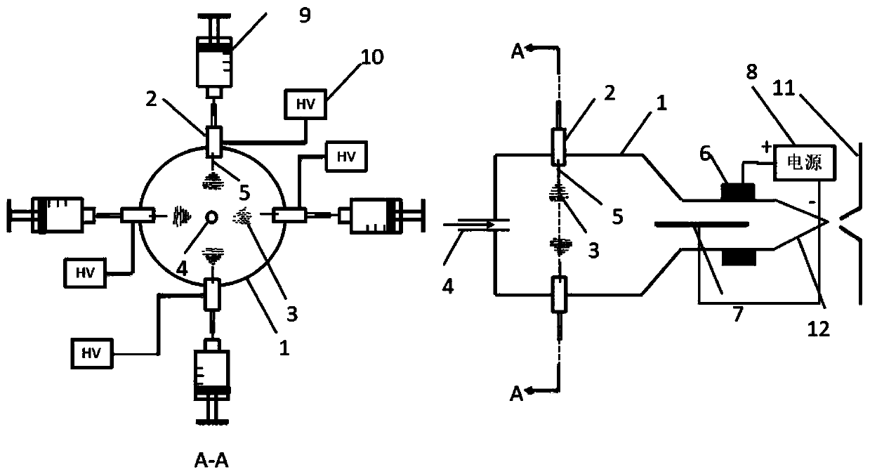
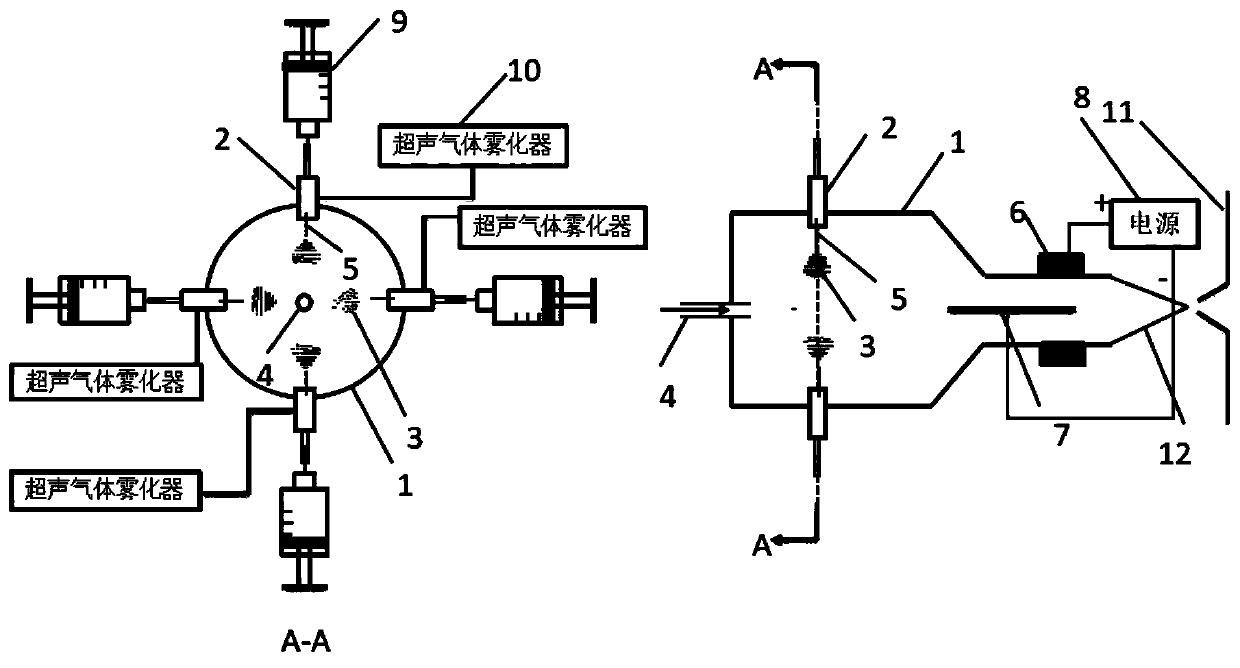
[0047] The structure of compound ionization source with four-channel sampling is as follows: figure 1 As shown, on the upper, lower, front and rear surfaces of the front-stage large cylindrical quartz glass tube 1, sampling slots 2 are vertically provided respectively. The outer sides of the four sampling slots are respectively connected to a DC high-voltage power supply 10. Before sample injection, the air inlet channel 4 is first opened to feed helium, and a high-voltage high-frequency power supply 8 is connected between the metal needle electrode 7 and the copper sheet ring electrode 6 to ensure A plasma flame 12 is pre-generated in the secondary ionization part of the latter stage. During sample injection, the four-way injector 9 injects the sample into the corresponding sample injection tank at a certain flow rate, and manually injects the sample. Under the action of DC high voltage, the sample solution is atomized into charged droplets 3 at the tip of the spray needle 5...
Embodiment 2
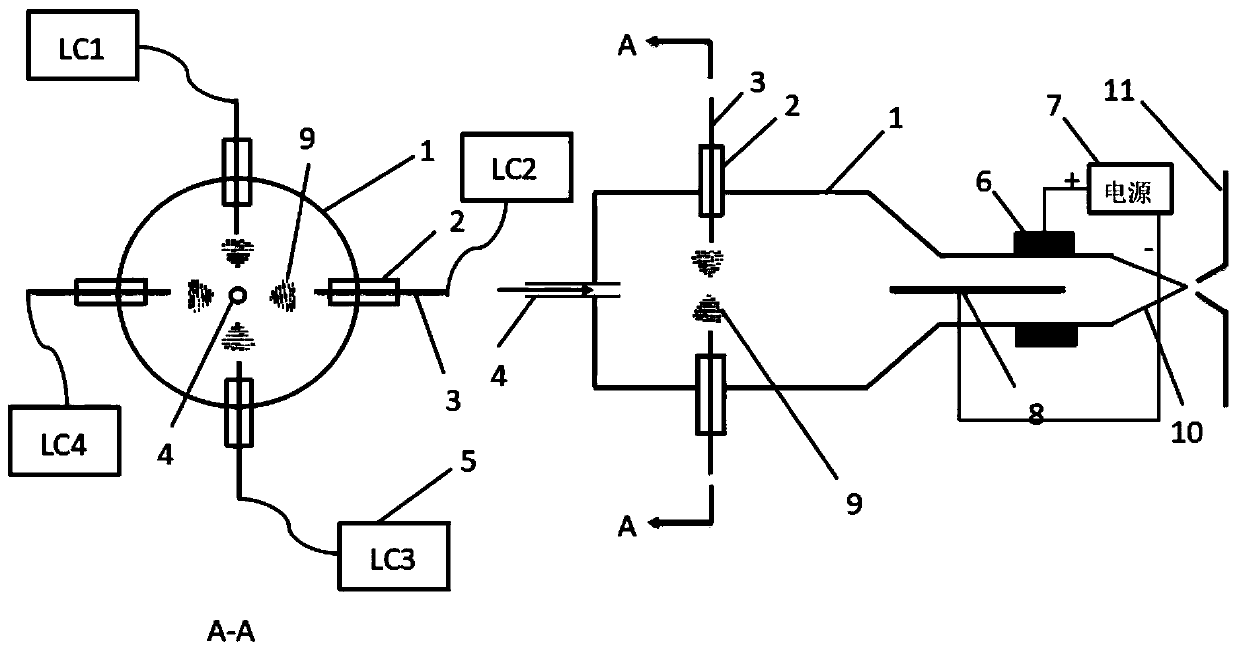
[0050] The structure of the four-channel injection ionization source combined with four liquid chromatography LCs is as follows: image 3 As shown, in this example, the four-way sampling grooves on the surface of the quartz glass tube are respectively connected to four liquid chromatographs through hollow capillaries, and the automatic sampling is directly through the liquid chromatograph, and the four-way LC combination can realize time-sharing multiplexing. use. When one liquid chromatograph finishes working and needs to deal with waste liquid and clean it, the other three liquid chromatographs can replace it and continue to inject samples. Figure 4Shown is the sequence diagram of four liquid chromatographs automatically injecting samples sequentially. Similarly, before sample injection, the inlet channel 4 is opened first, and the high-voltage and high-frequency power supply 7 is connected between the two electrodes to ensure that the plasma flame 10 is generated in advan...
PUM
 Abstract
Description
Claims
Application Information
 - R&D
- Intellectual Property
- Life Sciences
- Materials
- Tech Scout
- Unparalleled Data Quality
- Higher Quality Content
- 60% Fewer Hallucinations
Browse by: Latest US Patents, China's latest patents, Technical Efficacy Thesaurus, Application Domain, Technology Topic, Popular Technical Reports.
© 2025 PatSnap. All rights reserved.Legal|Privacy policy|Modern Slavery Act Transparency Statement|Sitemap|About US| Contact US: help@patsnap.com


