
High-temperature superconducting cable temperature measuring system

A high-temperature superconducting and temperature measurement technology, applied in the application field of power transmission technology, can solve the problems of destroying the temperature measurement performance of the temperature sensor, being subjected to electromagnetic interference, and monitoring the insulation performance of the cable, so as to reduce the fault processing time and achieve high stability and reliability , to ensure the effect of safe operation

Active Publication Date: 2019-06-07
SHENZHEN POWER SUPPLY BUREAU
View PDF8 Cites 10 Cited by
  • Summary
  • Abstract
  • Description
  • Claims
  • Application Information

AI Technical Summary

Problems solved by technology

[0005] (2) The high-temperature superconducting cable runs in liquid nitrogen, so its structure is quite different from that of conventional power cables. Its size is smaller and its structure is more compact. As a result, traditional temperature sensors such as thermal resistors and thermal resistors cannot be installed in superconducting cables. Monitor the temperature along the conductive cable (the insulation performance of the cable is damaged and the temperature measurement performance of the temperature sensor is interfered by electromagnetic interference)
[0006] The above two points limit the popularization and application of high-temperature superconducting cables in power grids, and because of the above-mentioned difficulty two, the current temperature monitoring range of superconducting cable systems is limited to the temperature monitoring of the terminal cooling system, and there has not been any temperature monitoring along the high-temperature superconducting cables. Measurement

Method used


Image

  • High-temperature superconducting cable temperature measuring system
  • High-temperature superconducting cable temperature measuring system
  • High-temperature superconducting cable temperature measuring system

Examples


Embodiment Construction

[0048] The following will clearly and completely describe the technical solutions in the embodiments of the present invention with reference to the accompanying drawings in the embodiments of the present invention. Obviously, the described embodiments are only some of the embodiments of the present invention, not all of them. Based on the embodiments of the present invention, all other embodiments obtained by persons of ordinary skill in the art without making creative efforts belong to the protection scope of the present invention.

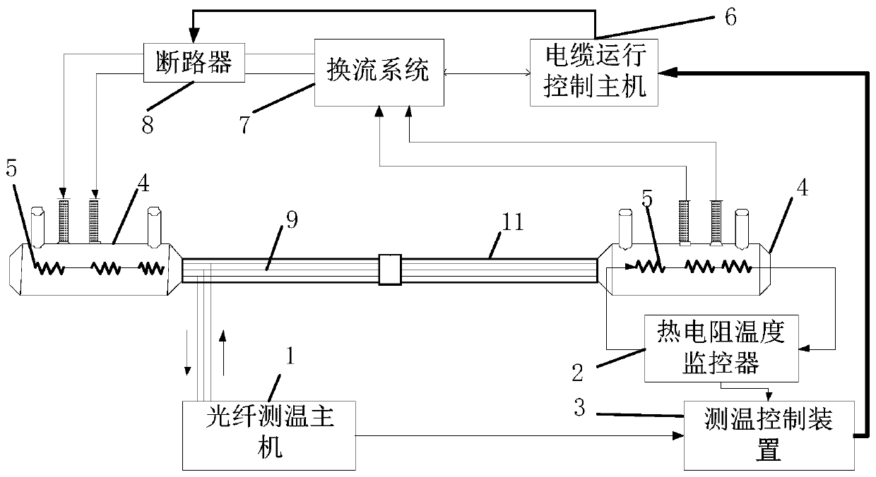
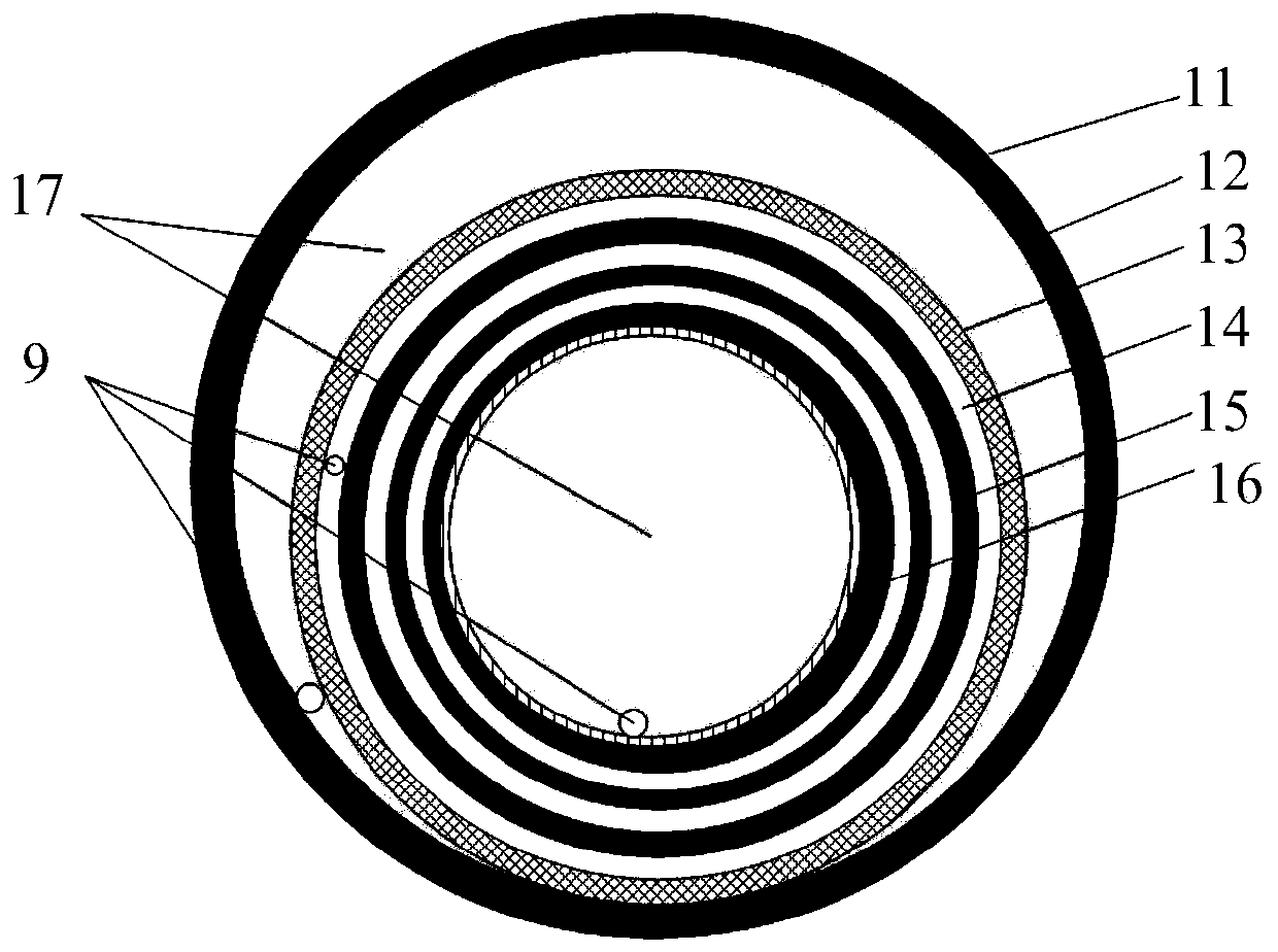
[0049] Such as figure 1 As shown, it is a schematic structural diagram of an embodiment of the high-temperature superconducting cable temperature measurement system provided by the present invention; combined with the subsequent drawings, in this embodiment, the embodiment of the present invention provides a high-temperature superconducting cable temperature The measuring system, applied in the interconnected high-temperature superconducting cabl...


PUM

PropertyMeasurementUnit
Widthaaaaaaaaaa

Abstract

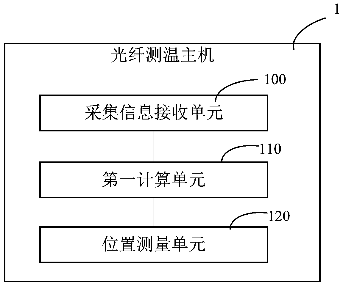
The invention discloses a high-temperature superconducting cable temperature measuring system. The system is applied to a high-temperature superconducting cable and a terminal cooling system which areconnected with each other. The system comprises a low-temperature temperature measuring optical fiber, a thermal resistor, an optical fiber optic temperature measurement host machine, a thermal resistor temperature monitor, and a temperature measurement control device; the low-temperature temperature measuring optical fiber is disposed in the high-temperature superconducting cable; the thermal resistor is arranged in the terminal cooling system; the optical fiber optic temperature measurement host machine is used for receiving temperature measurement information from various measurement points of the low-temperature temperature measurement optical fiber; the thermal resistor temperature monitor is used for receiving temperature information from the thermal resistor; the temperature measurement control device receives the temperature measurement information and the temperature information and performs evaluation and judgment according to the temperature measurement information and thetemperature information so as to determine the protection action and protection area of a cable operation control host machine connected with the temperature measurement control device, and control the cable operation control host machine to perform corresponding operation. The system of the invention has the advantages of convenient use and simple structure. With the system adopted, temperature abnormal points along the high-temperature superconducting cable can be accurately monitored and positioned; troubleshooting during the maintenance detection of the superconducting cable can be facilitated; a fault range can be narrowed; and fault processing time can be reduced.

Description

technical field [0001] The invention relates to the application field of power transmission technology, in particular to a high-temperature superconducting cable temperature measurement system. Background technique [0002] With the rapid development of my country's economy, the electricity consumption in many cities is increasing year by year, the power load in the central area of ​​the city has increased sharply, the transmission and distribution capacity has increased significantly, and issues such as reducing power grid losses and improving power grid operation stability have also been raised. At present, the power grid system has a lot of losses in the power transmission and distribution link, so all countries are looking for solutions to reduce power grid losses, among which superconducting materials are one of the most important solutions to reduce power grid losses, and the commercial production of high-temperature superconducting strips has promoted superconductivity...

Claims


Application Information

Patent Timeline
IPC IPC(8): G01K11/32G01K7/18G01K1/14G01K1/02
CPCG01K11/32G01K1/02G01K1/14G01K7/18Y02A30/00
Inventor 庞骁刚胡子珩廖建平章彬汪桢子汪伟
Owner SHENZHEN POWER SUPPLY BUREAU
Learn More