Self-operated pressure regulating valve assembled with improved valve seat fixing structure, and working mode thereof

A technology of pressure regulation and fixed structure, applied in valve shell structure, valve details, lift valve, etc., can solve the problems of waste of resources, small pressure regulation range of pressure regulating valve, inability to disassemble, etc., so as to reduce production and transportation costs and avoid resources. The effect of waste, reducing cost pressure

Active Publication Date: 2019-06-07
杭州泉通仪表阀门有限公司
View PDF5 Cites 0 Cited by
  • Summary
  • Abstract
  • Description
  • Claims
  • Application Information

AI Technical Summary

Problems solved by technology

[0003] Traditional self-operated pressure regulating valves on the market have relatively large limitations. Most of the valve seat structure and valve core are internally fixed and cannot be disassembled. As a pressure valve, the most easily damaged parts are the valve core and valve seat. The seat of the traditional regulating valve cannot be disassembled, and the valve core cannot be disassembled, which leads to the need to replace the entire pressure regulating valve when the internal valve core or valve seat of the pressure valve is faulty and damaged, which leads to a large waste of resources and greatly improves Production and transportation costs, at the same time, the traditional valve seat structure adopts a circular structure, which cannot effectively use the seat area, resulting in a small pressure adjustment range of the traditional pressure regulating valve, and low transportation efficiency

Method used


Image

  • Self-operated pressure regulating valve assembled with improved valve seat fixing structure, and working mode thereof
  • Self-operated pressure regulating valve assembled with improved valve seat fixing structure, and working mode thereof
  • Self-operated pressure regulating valve assembled with improved valve seat fixing structure, and working mode thereof

Examples


Embodiment Construction

[0034] The technical solutions of the present invention will be clearly and completely described below in conjunction with the embodiments. Apparently, the described embodiments are only some of the embodiments of the present invention, not all of them. Based on the embodiments of the present invention, all other embodiments obtained by persons of ordinary skill in the art without creative efforts fall within the protection scope of the present invention.

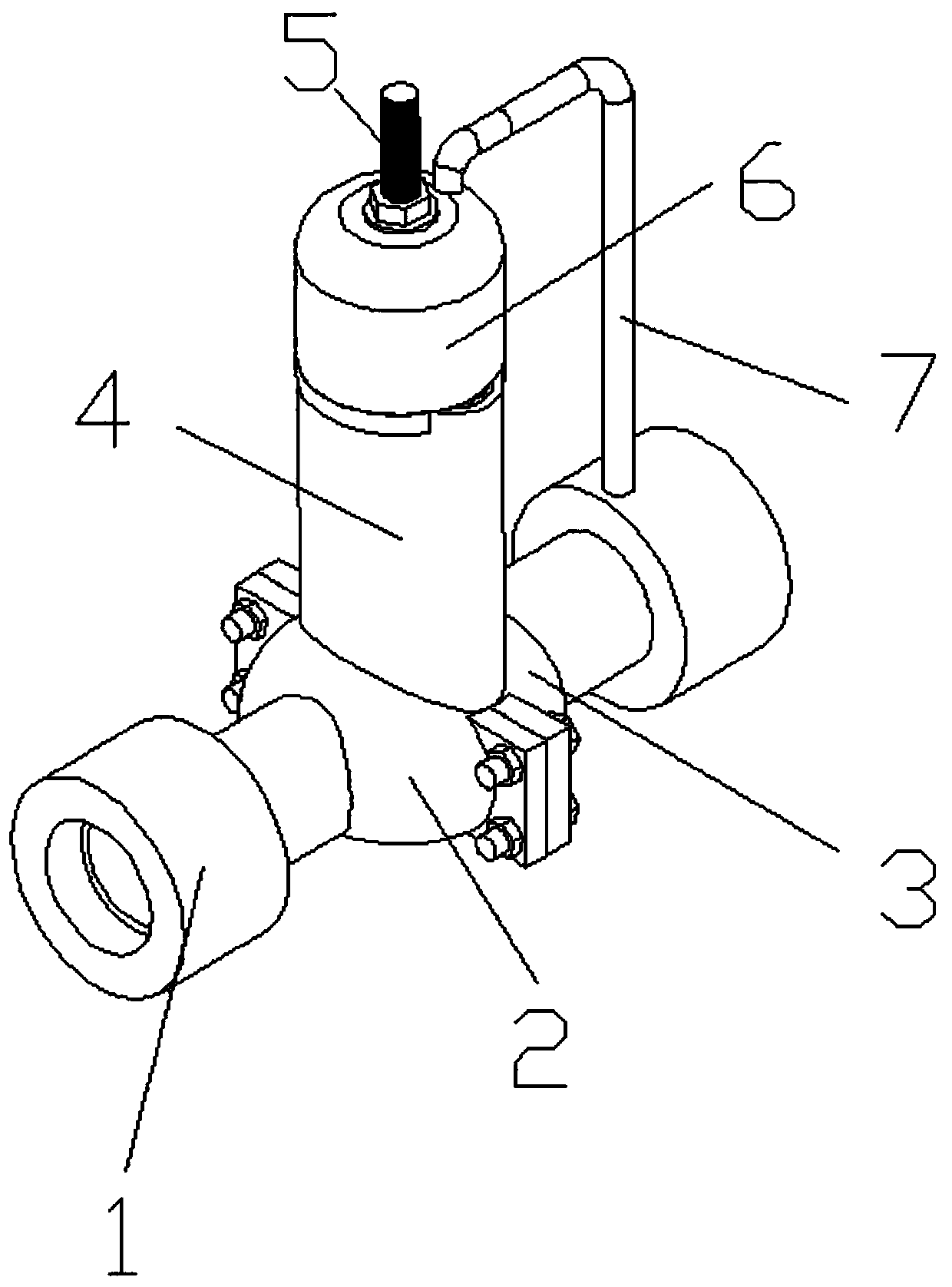
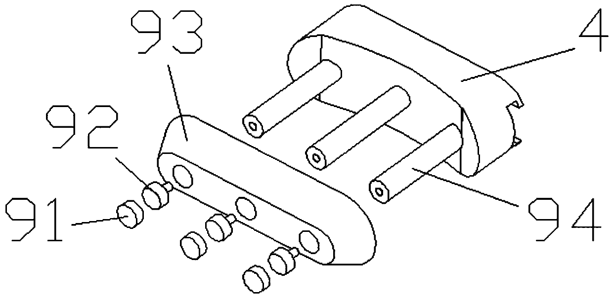
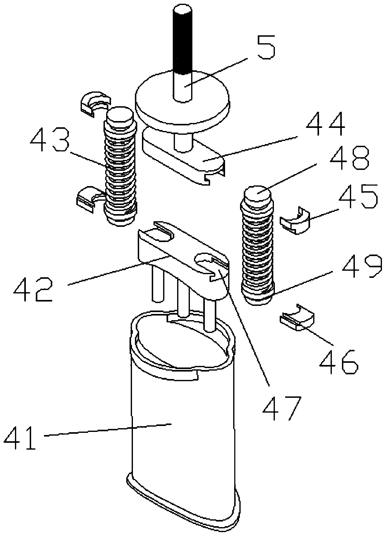
[0035] like Figure 1-4 As shown, a self-operated pressure regulating valve equipped with an improved valve seat fixing structure, including a connector 1, a first valve seat shell 2, a second valve seat shell 3, a pressure valve core control mechanism 4, and a rated pressure adjusting bolt 5 , From the pressure response device 6 and the liquid inlet pipe 7, the connector 1 is respectively installed at the position of the external pipe connection port of the first valve seat housing 2 and the second valve seat housing 3, th...


PUM


Abstract

The invention discloses a self-operated pressure regulating valve assembled with an improved valve seat fixing structure, and a working mode thereof. The self-operated pressure regulating valve assembled with the improved valve seat fixing structure structurally comprises a connector, a first valve seat shell, a second valve seat shell, a pressure valve element control mechanism, a rated pressureadjusting bolt, a self-pressure response device and a liquid inlet pipe. The self-operated pressure regulating valve assembled with the improved valve seat fixing structure provided by the invention is simple in structure and convenient to connect; the various parts are independent and demountable, and the disassembling and assembling processes are simple and not complicated, so that the self-operated pressure regulating valve assembled with the improved valve seat fixing structure has good freedom and extensibility and high practicability; the valve seat structure adopts a long strip shape, so that compared with a traditional circular valve seat, the utilization of the area of the valve seat is greatly improved, the section area of object conveying of the valve seat is increased, the conveying efficiency is improved, the pressure regulating range is large due to a large conveying area, and the practicability and a conveying effect of the self-operated pressure regulating valve are farsuperior to those of similar products on the market.

Description

technical field [0001] The invention belongs to the field of pipeline transportation, and in particular relates to a self-operated pressure regulating valve equipped with an improved valve seat fixing structure and its working method. Background technique [0002] Self-operated pressure regulating valves are divided into three series of self-operated pressure, differential pressure and flow regulating valves. The self-operated pressure regulating valve is divided into two types: before the valve and after the valve according to the position of the pressure taking point. When the pressure taking point is in front of the valve, it is used to adjust the pressure before the valve to be constant; when the pressure taking point is behind the valve, it is used to adjust the pressure behind the valve to be constant. . When the pressure before the valve and after the valve is introduced into both sides of the air chamber of the actuator, the self-operated differential pressure regul...

Claims


Application Information

Patent Timeline
Patent Type & Authority Applications(China)
IPC IPC(8): F16K17/06F16K1/36F16K1/46F16K27/02
Inventor 裘艳琴张姗朱廷顺
Owner 杭州泉通仪表阀门有限公司
Why Eureka
Try Eureka