
Train

A technology for trains and train tubes, which is applied in the directions of railway car body parts, railway couplings, transportation and packaging, etc., which can solve the problems of large space occupied by the car end, difficult design of the length of the hose 1, and breakage, etc., to achieve space occupation big effect

Inactive Publication Date: 2019-05-28
CRRC TANGSHAN CO LTD
View PDF11 Cites 4 Cited by
  • Summary
  • Abstract
  • Description
  • Claims
  • Application Information

AI Technical Summary

Problems solved by technology

[0007] 2) The hose 1 is bulky and takes up a lot of space at the car end;
[0008] 3) The design of the length of the hose 1 is difficult. If it is too long, it will easily collide with the track. If it is too short, it will be difficult to meet the requirements of the length margin of the hose 1 in complex lines, and it may be pulled or broken.
[0011] 1) When the vehicle is on the curve, due to the large swing of the coupler, the flexible connection of the hose 3 must bear the horizontal and vertical swing of the coupler. It is difficult to meet the length margin requirements under large swings when passing through complex lines, and may even be pulled or broken;
[0012] 2) This connection method is only applicable to fixed marshalling vehicles;
[0013] 3) When the first and second positions of the vehicle are switched, the connection cannot be made, because it is distributed on both sides of the coupler. If a vehicle changes the end of the first and second positions, the interface on the same side will be transferred to the other side, and it needs to be located under the coupler. Cross connection will inevitably interfere with the coupler, resulting in poor flexibility

Method used


Image

  • Train
  • Train
  • Train

Examples


Embodiment Construction

[0044] The principles and features of the present invention are described below in conjunction with the accompanying drawings, and the examples given are only used to explain the present invention, and are not intended to limit the scope of the present invention.

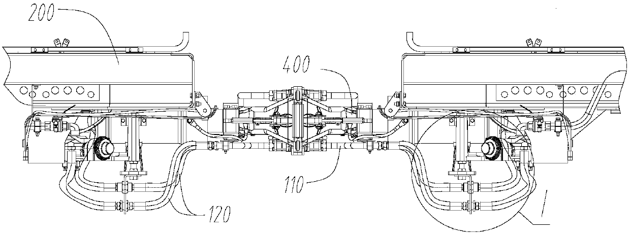
[0045] Figure 3 to Figure 6 As shown, the present invention relates to a train, the train includes an air brake system, and the air brake system includes an air supply brake pipeline 300 installed at the bottom of the train carriage 200, between adjacent carriages 200 The air supply brake pipeline 300 is connected through the vehicle-end connecting device 100, and the vehicle-end connecting device 100 includes:

[0046] The connecting pipe seat 110 is installed below the centering position of the coupler 400 of the adjacent carriage 200; the connecting pipe seat 110 is hollow inside, and its middle can be separated as the car coupler 400 is separated; The two ends of the connecting tube base 110 are provided with ...


PUM


Abstract

The invention relates to a train. Air supply braking pipelines located between adjacent carriages of the train are connected through train end connecting devices; each train end connecting device comprises a connecting pipe seat mounted below the centering position of a coupling gear of the adjacent carriages as well as connecting hoses, one end of each connecting hose is connected with a connecting port, and the other end of each connecting hose is connected with the air supply braking pipeline of the corresponding carriage. The train has the advantage that the overall connecting pipelines occupy small space, transverse and longitudinal swinging of the train is effectively borne, and hose wear and pulling and dragging risks due to interference formed by the hoses and the coupling gears inthe swinging process are avoided; the air supply braking pipelines are not required to be cut off manually again during disassembling and reconnecting; by means of the connecting pipe seats, the pipelines are collected to a longitudinal center of the train, so that expansion and contraction quantity of the pipelines due to coupling gear swinging is greatly reduced, pulling and dragging of the connecting hoses are avoided, and randomness and flexibility of connection are increased. The train is applicable to all vehicle models adopting double-pipe air supply.

Description

technical field [0001] The invention relates to the field of connection devices for train braking system pipelines, in particular to a train. Background technique [0002] The double-pipe air supply is the air supply mode of the indirect-acting air brake system, which is widely used in rail vehicles at home and abroad, and is one of the main air supply methods of the rail vehicle brake system. [0003] The brake hose is designed to connect the brake main pipes of adjacent vehicles. It should not hinder the smooth flow of pressure air when the train passes through the curve or the vehicles expand and contract. Its safety performance directly affects the operation of rail vehicles. Safety. However, due to the operating conditions of rail vehicles and the influence of line conditions, different degrees of swing will occur during the operation of the vehicle, especially when the vehicle passes through a curve, there will be a large swing. At this time, the coupler swings freque...

Claims


Application Information

Patent Timeline
Patent Type & Authority Applications(China)
IPC IPC(8): B61H11/06B60T17/04
CPCB60T17/04B61G5/08B61H11/06
Inventor 张新永张丽丽李庚焦东明王琳梁建全张冬冬张兴旺申云彤李化明
Owner CRRC TANGSHAN CO LTD
Learn More