Heat exchange tube wound ribbon, heat exchanger and air conditioner

A technology of heat exchange tubes and heat exchangers, which is applied in evaporators/condensers, tubular elements, heat exchange equipment, etc., and can solve the problems of blocking the air side flow path, accumulation of condensed water film, and negative impact on the cruising range of automobiles, etc. problems, to achieve the effect of strengthening drainage, inhibiting the formation of water film, and increasing the contact area

Pending Publication Date: 2019-05-24
GREE ELECTRIC APPLIANCES INC
View PDF0 Cites 0 Cited by
  • Summary
  • Abstract
  • Description
  • Claims
  • Application Information

AI Technical Summary

Problems solved by technology

In the process of using the insert heat exchanger and the microchannel heat exchanger, many shortcomings that need to be overcome are exposed: under the same heat exchange capacity, the mass of the insert heat exchanger is relatively large, which increases the burden on the car body and affects the cruising range of the car. The improvement of the micro-channel heat exchanger has a negative impact; the heat transfer effect of the micro-channel heat exchanger is weaker than that of the insert heat exchanger, and in the working environment of high humidity and low flow rate on the air side, condensate accumulation and water will appear on the surface of the micro-channel heat exchanger. When the membrane blocks the flow path on the air side
At present, the situation of the above two mainstream vehicle air-conditioning heat exchangers is not conducive to the promotion of vehicle energy-saving technology

Method used


Image

  • Heat exchange tube wound ribbon, heat exchanger and air conditioner
  • Heat exchange tube wound ribbon, heat exchanger and air conditioner
  • Heat exchange tube wound ribbon, heat exchanger and air conditioner

Examples


Embodiment Construction

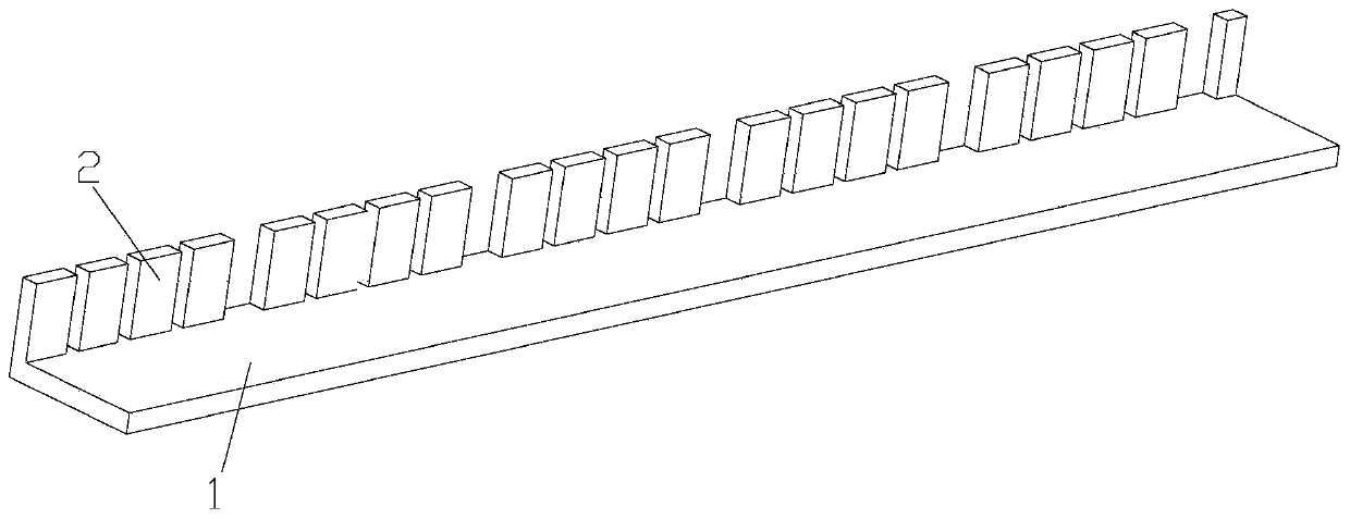
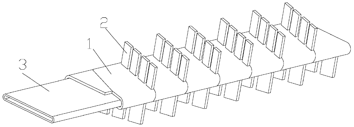
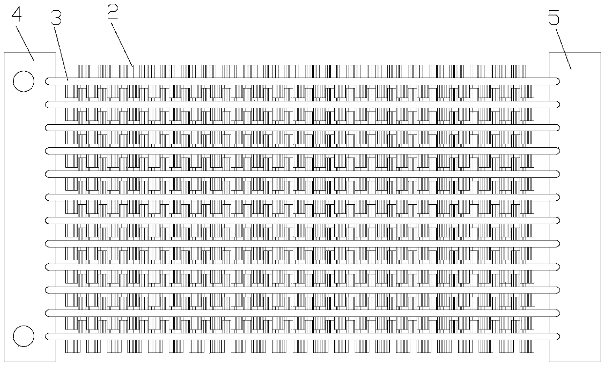
[0027] see in conjunction Figure 1 to Figure 3 As shown, according to the embodiment of the present application, the heat exchange tube tape is used to be wound outside the heat exchange flat tube 3 , and the heat exchange tube tape includes a tape body 1 and multiple sets of heat exchange tubes arranged on the tape body 1 . Fins, each group of heat exchange fins includes at least two fin units 2, adjacent groups of heat exchange fins are respectively located on different heat exchange surfaces of the heat exchange flat tube 3, and the fin units 2 of the same group are arranged at intervals . The top of the fin unit 2 in this embodiment refers to the end of the fin unit 2 away from the winding body 1 .

[0028] The heat exchange tube tape of the present application includes a tape body 1 and heat exchange fins arranged on the tape body 1. When using the heat exchange tube tape, the tape body 1 can be wound on the heat exchange flat tube 3 surface, thereby increasing the con...


PUM


Abstract

The application provides a heat exchange tube wound ribbon, a heat exchanger and an air conditioner. The heat exchange tube wound ribbon is used for being wound outside a heat exchange flat tube (3),and comprises a wound ribbon body (1) and a plurality of groups of heat exchange fins arranged on the wound ribbon body (1); each group of heat exchange fins comprises at least two fin units (2); theadjacent groups of heat exchange fins are separately positioned on different heat exchange surfaces of the heat exchange flat tube (3); and the same groups of fin units (2) are arranged at intervals.According to the heat exchange tube wound ribbon, the condition that fin holes are blocked by water films under the conditions of low air pressure and high humidity can be effectively avoided, and theheat exchange effect of the heat exchanger is improved.

Description

technical field [0001] The application belongs to the technical field of air conditioning, and in particular relates to a heat exchange tube coil, a heat exchanger and an air conditioner. Background technique [0002] At present, most of the air-conditioning evaporators installed in passenger cars use insert heat exchangers and micro-channel heat exchangers. In the process of using the insert heat exchanger and the microchannel heat exchanger, many shortcomings that need to be overcome are exposed: under the same heat exchange capacity, the mass of the insert heat exchanger is relatively large, which increases the burden on the car body and affects the cruising range of the car. The improvement of the micro-channel heat exchanger has a negative impact; the heat transfer effect of the micro-channel heat exchanger is weaker than that of the insert heat exchanger, and in the working environment of high humidity and low flow rate on the air side, condensate accumulation and wate...

Claims


Application Information

Patent Timeline
Patent Type & Authority Applications(China)
IPC IPC(8): F28F1/12F25B39/02B60H1/00
Inventor 王雪东刘新昌邹泳坚郭瑞安王婧雅
Owner GREE ELECTRIC APPLIANCES INC
Why Eureka
Try Eureka