


Quick Research
Generate reliable direction feasibility study reports for your R&D in just a few steps.

Technical Q&A
Discover and master advanced knowledge NOW. Basics, ideas, possibilities, all at once.

Find Solutions
As an expert in R&D theories, this can generate solutions to your technical problems instantly.

Evaluate Feasibility
Analyze your overall solution with one click, know your potential R&D risks in advance.

Monitor Landscape
Get weekly tech updates, stay abreast of the latest tech innovations and key insights.
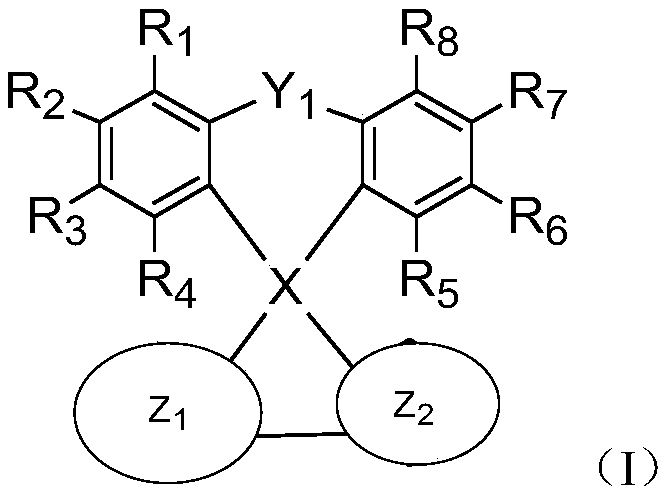
Spiro compound and application thereof
A spiro compound and condensing technology, applied in the field of organic electroluminescent materials, can solve the problems of poor film formation and great influence on the long-term stability of the device, and achieve the effect of low turn-on voltage and high external quantum efficiency
- Summary
- Abstract
- Description
- Claims
- Application Information
AI Technical Summary
Problems solved by technology
Method used
Image

Examples
Embodiment 1
[0110] Embodiment 1: the synthesis of compound TM1
[0111] step 1
[0112]
[0113] Compound C-1 (3.5g, 12.2mmol) was added to 50mL of tetrahydrofuran, and n-butyllithium (5.8mL, 14.6mmol) was added dropwise at a low temperature of -78°C. After the reaction system continued to stir for 1 hour, the temperature was maintained and slowly A 10 mL solution of compound C-2 (10.8 mmol) was added and stirred for another 2 hours, then raised to room temperature and stirred for 12 hours. The reaction system was extracted with ethyl acetate and recrystallized from diethyl ether to obtain an intermediate. Add the obtained intermediate to 30 mL of acetic acid, raise the temperature to 80°C, add 1 drop of concentrated hydrochloric acid, reflux for 2 hours, cool to room temperature, and filter to obtain compound C-3. Yield 59%.
[0114] step 2
[0115]
[0116] Compound C-3 (4.1g, 10mmol) was dissolved in 50mL DMF, then NBS (2.1g, 12mmol) was slowly added dropwise, and 50mL of dist...
Embodiment 2
[0122] Embodiment 2: the synthesis of compound TM2
[0123] step 1
[0124]
[0125] Compound C-3 (4.1g, 10mmol) was dissolved in 50mL DMF, then NBS (4.2g, 24mmol) was slowly added dropwise, and 50mL distilled water was added dropwise under stirring, and stirring was continued for 1 hour after the addition was completed, and the precipitate was filtered and used Recrystallize from n-hexane to obtain compound C-6. Yield 34%.
[0126] step 2
[0127]
[0128] Compound C-6 (5.7g, 10mmol) and compound C-7 (7.7g, 22mmol), tetrakistriphenylphosphine palladium (1.2g, 1mmol), potassium carbonate (5.6g, 120mmol), were added to 100mL toluene, In a mixed solvent of 100mL dioxane and 20mL water, reflux the reaction for 12 hours, extract with ethyl acetate, and carry out column chromatography to obtain the target compound TM2. Yield 27%.
[0129] Mass spectral data: [M+]=1012.
Embodiment 3
[0131] step 1
[0132]
[0133] Compound C-6 (5.7g, 10mmol) and compound C-5 (3.3g, 11mmol), tetrakis triphenylphosphine palladium (0.6g, 0.5mmol), potassium carbonate (2.8g, 60mmol), was added to 50mL toluene , 50 mL of dioxane, and 10 mL of water in a mixed solvent, refluxed for 12 hours, extracted with ethyl acetate, and carried out column chromatography to mention compound C-8. Yield 30%.
[0134] step 2
[0135]
[0136] Compound C-8 (7.9g, 10mmol) and compound C-9 (1.3g, 11mmol), tetrakis triphenylphosphine palladium (0.6g, 0.5mmol), potassium carbonate (2.8g, 60mmol), was added to 50mL toluene , 50mL dioxane, and 10mL water in a mixed solvent, reflux for 12 hours, extract with ethyl acetate, and carry out column chromatography to mention compound TM3. Yield 37%.
[0137] Mass spectral data: [M+]=786.
PUM
| Property | Measurement | Unit |
|---|---|---|
| Nmr | aaaaa | aaaaa |
Abstract
Description
Claims
Application Information
 - R&D Engineer
- R&D Manager
- IP Professional
- Industry Leading Data Capabilities
- Powerful AI technology
- Patent DNA Extraction
Browse by: Latest US Patents, China's latest patents, Technical Efficacy Thesaurus, Application Domain, Technology Topic, Popular Technical Reports.
© 2024 PatSnap. All rights reserved.Legal|Privacy policy|Modern Slavery Act Transparency Statement|Sitemap|About US| Contact US: help@patsnap.com