System for an utility vehicle comprising a screw compressor and an electric motor

An electric motor, screw technology, applied in the components of the pumping device for elastic fluid, machine/engine, rotary piston machine, etc., can solve the problem of increasing the inertia of the system, and achieve the effect of low cost and space saving

Inactive Publication Date: 2019-05-21
KNORR BREMSE SYST FUER NUTZFAHRZEUGE GMBH
View PDF16 Cites 2 Cited by
  • Summary
  • Abstract
  • Description
  • Claims
  • Application Information

AI Technical Summary

Problems solved by technology

This increases the inertia of the system
In addition, the oil cooler has to be mechanically mounted and fastened, either by means of several mountings located around it or by a single mounting, which requires additional fastening means and installation space

Method used


Image

  • System for an utility vehicle comprising a screw compressor and an electric motor
  • System for an utility vehicle comprising a screw compressor and an electric motor
  • System for an utility vehicle comprising a screw compressor and an electric motor

Examples


Embodiment Construction

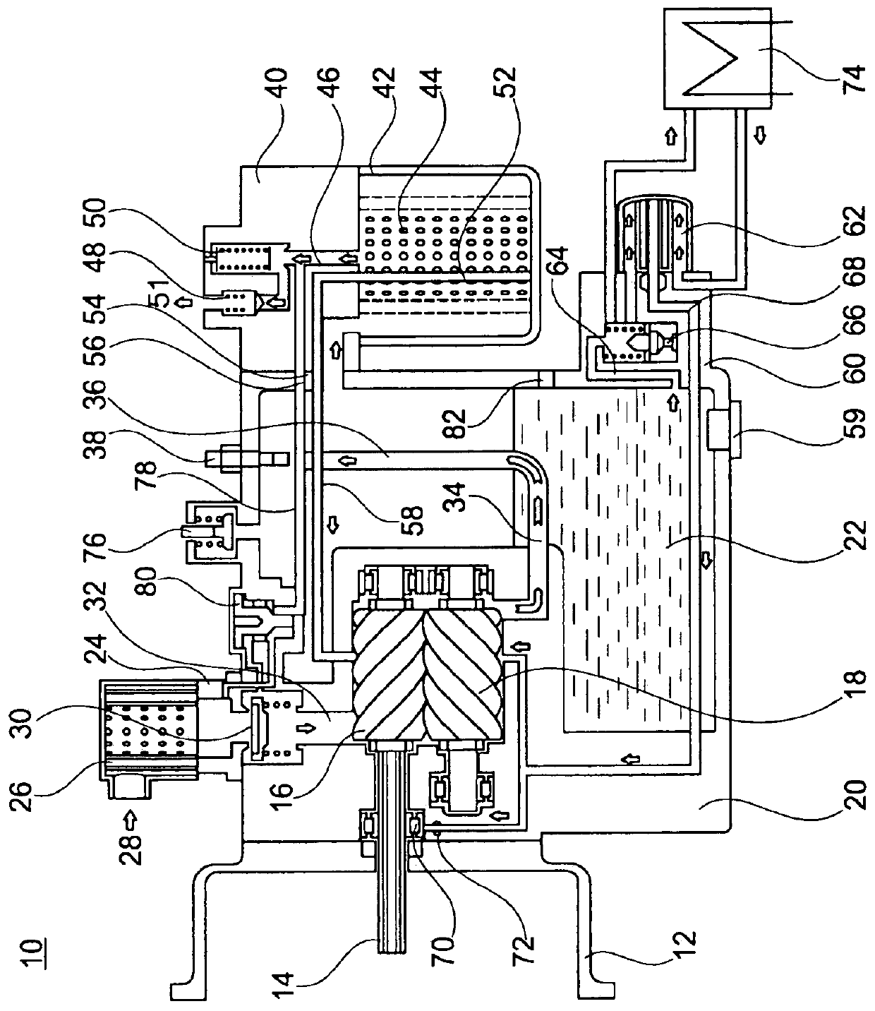
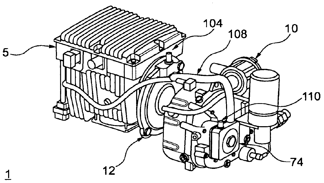
[0026] figure 1 A screw compressor 10 in the sense of an embodiment of the invention is shown in a schematic sectional view.

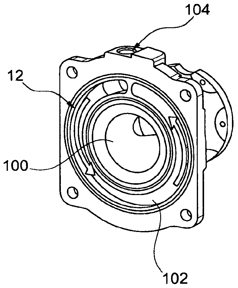
[0027] The screw compressor 10 has a fastening flange 12 for the mechanical fastening of the screw compressor 10 to an electric motor (not further shown here).

[0028] However, the input shaft 14 is also shown, via which the torque of the electric motor is transmitted to one of the two spindles 16 and 18 , namely the spindle 16 .

[0029] The screw 18 meshes with the screw 16 and is driven via the screw 16 .

[0030] The screw compressor 10 has a housing 20 in which the main components of the screw compressor 10 are installed.

[0031] Housing 20 is filled with oil 22 .

[0032] An inlet connection 24 is provided on the housing 20 of the screw compressor 10 on the air inlet side. The inlet connection 24 is designed in such a way that an air filter 26 is arranged thereon. Furthermore, air inlet openings 28 are arranged radially on the air inlet co...


PUM


Abstract

The invention relates to a system (1) for a utility vehicle comprising a screw compressor (10) and an electric motor (5), said electric motor (5) driving the screw compressor (10). The electric motor(5) is connected to the screw compressor (10) by means of a flange (12) which comprise at least one cooling connection (104, 106) and a cooling channel is provided in the flange (12).

Description

technical field [0001] The invention relates to a system for a commercial vehicle comprising a screw compressor and an electric motor. Background technique [0002] Screw compressors for commercial vehicles are already known from the prior art. Such screw compressors are used to supply the compressed air required, for example, to the brake systems of commercial vehicles. [0003] Against this background, in particular oil-filled compressors, in particular screw compressors, are known, in which the task of regulating the oil temperature is addressed. This is usually done in that there is an external oil cooler which is connected to the oil-filled compressor and the oil circuit via a thermostatic valve. The oil cooler is here a heat exchanger which has two circuits separated from one another, wherein a first circuit is provided for hot liquid, ie compressor oil, and a second circuit is used for cooling the liquid. Air, a mixture of water and antifreeze or other oils can be ...

Claims


Application Information

Patent Timeline
Patent Type & Authority Applications(China)
IPC IPC(8): F04C27/00F04C29/00F04C29/02F04C29/04F04C18/08F04C18/16
CPCF04C18/16F04C27/006F04C29/026F04C29/04F04C2240/30F04C2240/40F04C23/02F04C2210/1005F04C2210/221F05B2210/12F05B2210/16F05B2260/212
Inventor G·埃布拉尔J-B·马雷斯科J·梅拉尔T·魏因霍尔德H·卡尔森
Owner KNORR BREMSE SYST FUER NUTZFAHRZEUGE GMBH
Why Eureka
Try Eureka