
A frame synchronization signal generation method and projection equipment

A frame synchronization signal and signal technology, applied in the field of micro-projection, can solve the problems of affecting the stability of the projection image, the deviation of the projection position of the laser beam, and the change of the starting position of the image.

Active Publication Date: 2019-05-21
GOERTEK OPTICAL TECH CO LTD
View PDF3 Cites 13 Cited by
  • Summary
  • Abstract
  • Description
  • Claims
  • Application Information

AI Technical Summary

Problems solved by technology

However, due to the circuit structure of the projection equipment and the MEMS body (such as the use of electromagnetic force or electrostatic force to drive the scanning galvanometer requires a certain response time), there is a certain delay in the actual operation of the MEMS scanning galvanometer.
Therefore, even if the timing of the laser beam emitted by the laser corresponds to the scanning period of the driving signal of the fast axis of the scanning galvanometer and the scanning period of the driving signal of the slow axis of the scanning galvanometer, the projection position of the laser beam on the light curtain will still be shifted, resulting in The starting position of each frame of image changes, which affects the stability of the projected picture

Method used


Image

  • A frame synchronization signal generation method and projection equipment
  • A frame synchronization signal generation method and projection equipment
  • A frame synchronization signal generation method and projection equipment

Examples


Embodiment Construction

[0075] In order to enable those skilled in the art to better understand the solutions of the present application, the technical solutions in the embodiments of the present application will be clearly and completely described below in conjunction with the drawings in the embodiments of the present application.

[0076] In some processes described in the specification and claims of the present application and the description in the above-mentioned drawings, multiple operations appearing in a specific order are included, but it should be clearly understood that these operations may not be performed in the order in which they appear herein Execution or parallel execution, the serial numbers of the operations, such as 101, 102, etc., are only used to distinguish different operations, and the serial numbers themselves do not represent any execution order. Additionally, these processes can include more or fewer operations, and these operations can be performed sequentially or in paral...


PUM


Abstract

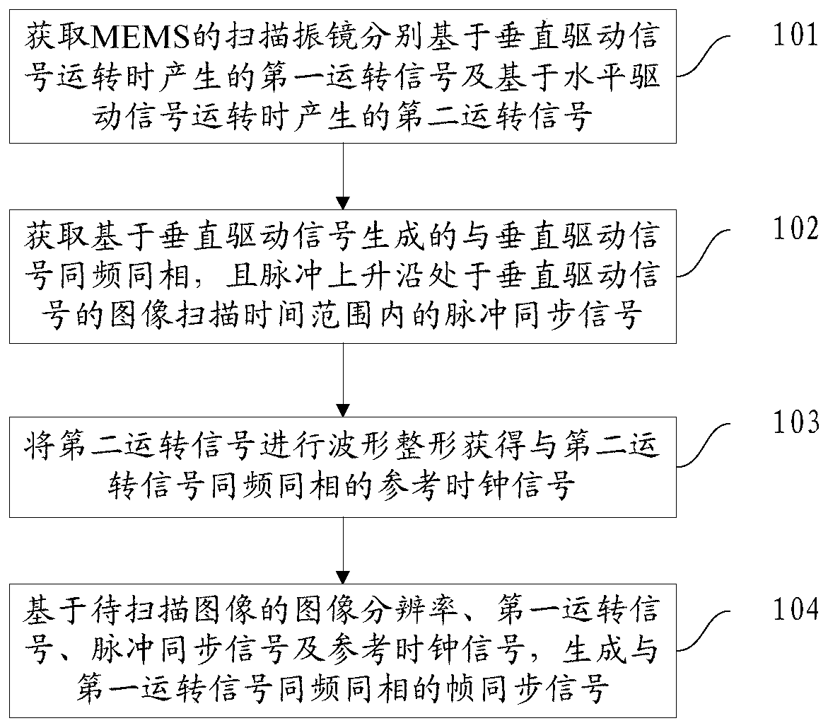
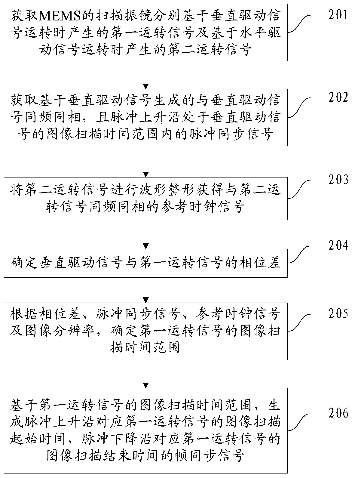
The embodiment of the invention provides a frame synchronization signal generation method and projection equipment. The method comprises the steps that a first operation signal generated when a scanning galvanometer of an MEMS operates on the basis of a vertical driving signal and a second operation signal generated when the scanning galvanometer operates on the basis of a horizontal driving signal are acquired; And acquiring a pulse synchronization signal which is generated based on the vertical driving signal, has the same frequency and the same phase as the vertical driving signal, and hasa pulse rising edge within an image scanning time range of the vertical driving signal. And performing waveform shaping on the second operation signal to obtain a reference clock signal with the samefrequency and phase as the second operation signal. And based on the image resolution of the to-be-scanned image, the first operation signal, the pulse synchronization signal and the reference clock signal, generating a frame synchronization signal with the same frequency and the same phase as the first operation signal, so that the laser lights the to-be-scanned image by taking the frame synchronization signal as a frame start time sequence. The stability of the projection picture can be greatly improved.

Description

technical field [0001] The embodiments of the present application relate to the technical field of micro-projection, and in particular, to a method for generating a frame synchronization signal and a projection device. Background technique [0002] Compared with the common LCD (liquid crystal micro-projection technology) transmission micro-projection, DLP (digital optical processing technology) reflective micro-projection and LCOS (liquid crystal on silicon) reflective micro-projection, the laser scanning projector (LBS) has a simple structure, small size, It has the advantages of small optical path loss, low power consumption, wide color range, high contrast, high resolution, and no need for focusing. [0003] In the LBS projection system, MEMS (Microelectromechanical Systems, Microelectromechanical Systems) and lasers are the main components. The scanning galvanometer in MEMS (Microelectromechanical Systems, Microelectromechanical Systems) is a key device in a laser scann...

Claims


Application Information

Patent Timeline
Patent Type & Authority Applications(China)
IPC IPC(8): H04N9/31
Inventor 高文刚
Owner GOERTEK OPTICAL TECH CO LTD
Learn More