Flat plate dryer suitable for particle drying conducted after wet granulation of urea formaldehyde molding material and particle drying method

A urea-formaldehyde molding compound and wet granulation technology, applied in progressive dryers, drying solid materials, drying gas layout, etc., can solve problems such as post-processing of gas that does not involve moisture, high energy consumption, heat loss, etc.

Pending Publication Date: 2019-05-21
溧阳市乔森塑料有限公司
View PDF3 Cites 0 Cited by
  • Summary
  • Abstract
  • Description
  • Claims
  • Application Information

AI Technical Summary

Problems solved by technology

But still there are many technical problems, the one, in its vacuum mixing step, because will make the final water content of material drop to about 4%, so reaction and vacuum dehydration time will be as long as 5 hours, and make energy consumption relatively high
Second, if the color of the material is not well controlled in the vacuum mixing step, the color of the obtained molding compound product cannot be adjusted, and in severe cases, this batch of products will be scrapped
Third, for the finished molding compound, if other indicators such as demoulding performance, curing time and moisture content are not suitable for the user's requirements, adjustments cannot be made, and in severe cases, the product will also be scrapped
However, Document 1 has the following technical problems: (1) The heat source of the drying device adopts electric heating wires, and the blowing blades are driven by a motor so that the outside air passes through the electric heating wires in a heated state and then blows to the air heater on the partition in the drying box. The mixed urea-aldehyde molding compound is heated and dried and boiled. Since the heating wire is arranged at the bottom of the side of the drying box, the blowing blade driven by the motor needs to provide the blowing force to make the material boil in the box, so the energy consumption is relatively high. Big
(2) Since the blowing blades are located at the bottom of the side of the drying box, and the air outlet is located below the lowermost partition, although there are multiple ventilation holes on each partition, it is still easy to damage the surface of the partition that is not the bottom. The wind blind area is caused by the material, that is, many parts of the surface materials of the remaining partitions are not affected by the hot air, and are easily blocked by the materials on the next layer of partitions during the sliding process of the materials, causing blockage
However, Document 2 also has certain technical problems: (1) Since the electric heater is used for heating, and the electric heater is installed on the rear side of the conveying mesh belt, the heat loss during the hot air transfer process is relatively large, and the heat conduction and heat utilization are limited , higher energy consumption
(2) The hot air in this document still uses the traditional bottom-up method to flow through the material instead of directly blowing on the material, so the heat is partially lost from the beginning
(3) The dryer in Document 2 is also equipped with a dehumidification outlet and a dehumidification fan. The humid air is dehumidified from the dehumidification outlet through the dehumidification fan. However, Document 2 does not involve how to post-process the humid gas, which is not conducive to environmental protection.
However, this document has the following technical problems: (1) The name of the heat exchanger is wrong. If heating is to be performed, the name heat exchanger or heat exchanger should be used
(2) Undisclosed medium for heat exchange

Method used


Image

  • Flat plate dryer suitable for particle drying conducted after wet granulation of urea formaldehyde molding material and particle drying method
  • Flat plate dryer suitable for particle drying conducted after wet granulation of urea formaldehyde molding material and particle drying method
  • Flat plate dryer suitable for particle drying conducted after wet granulation of urea formaldehyde molding material and particle drying method

Examples


Embodiment 1)

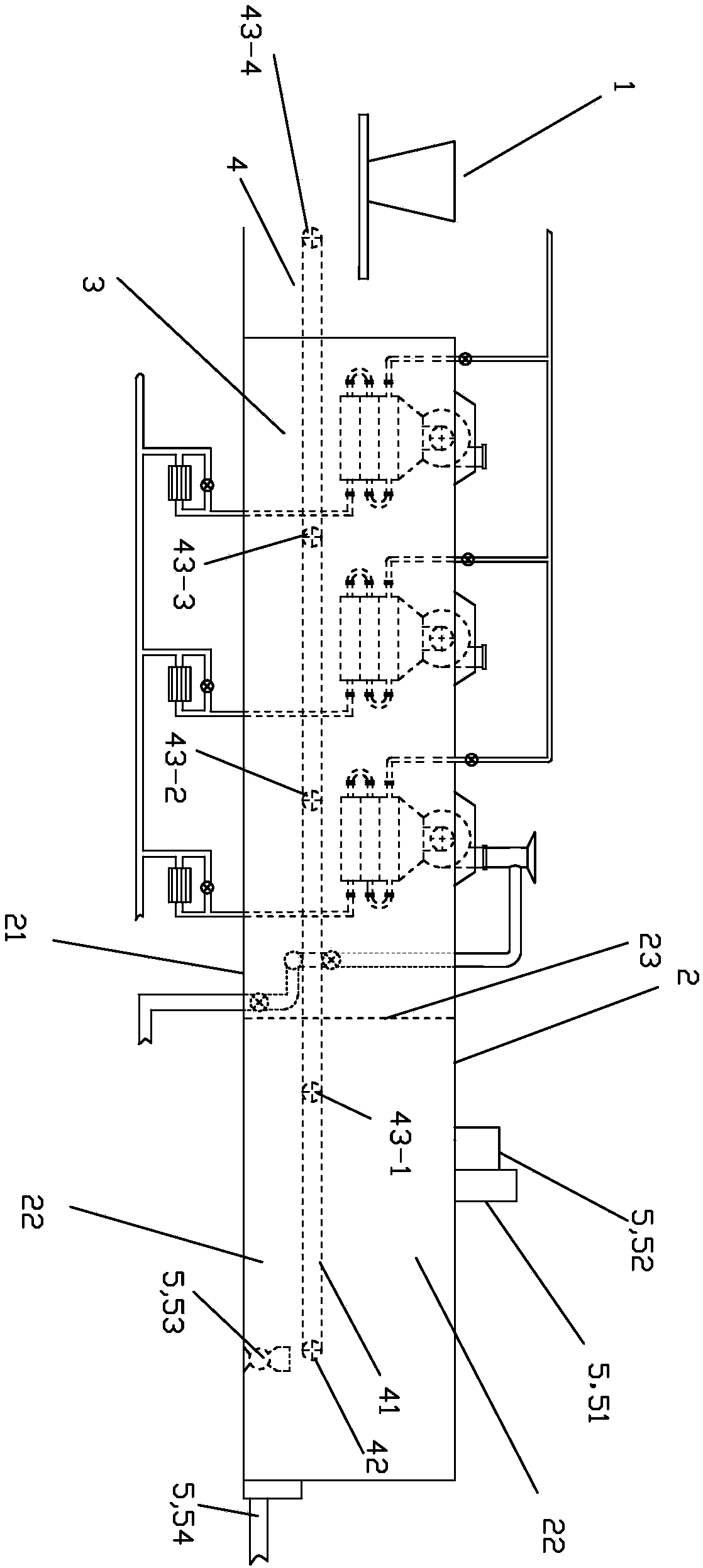
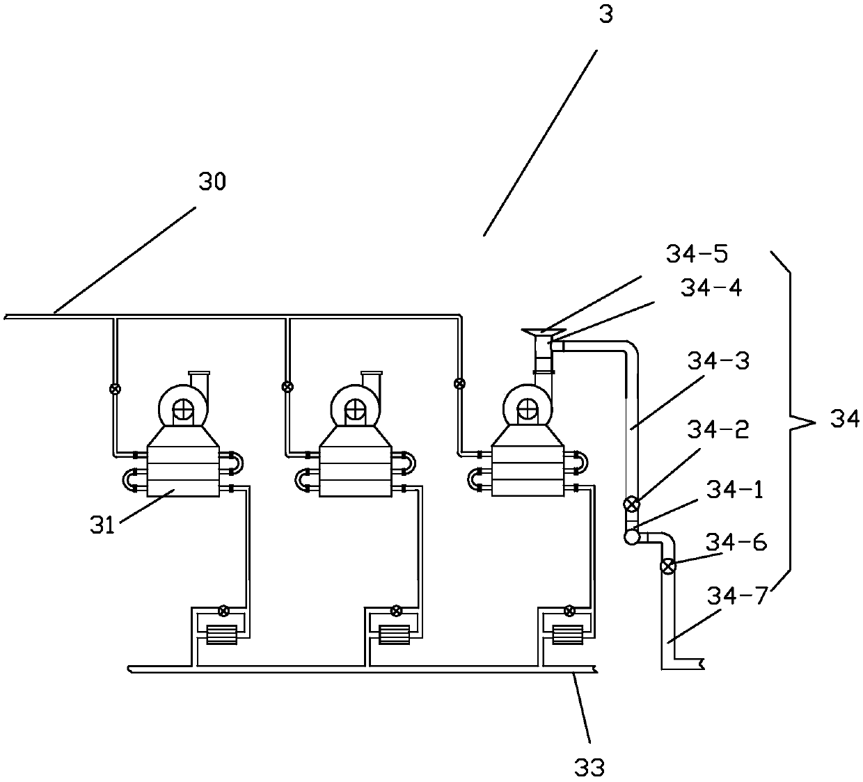
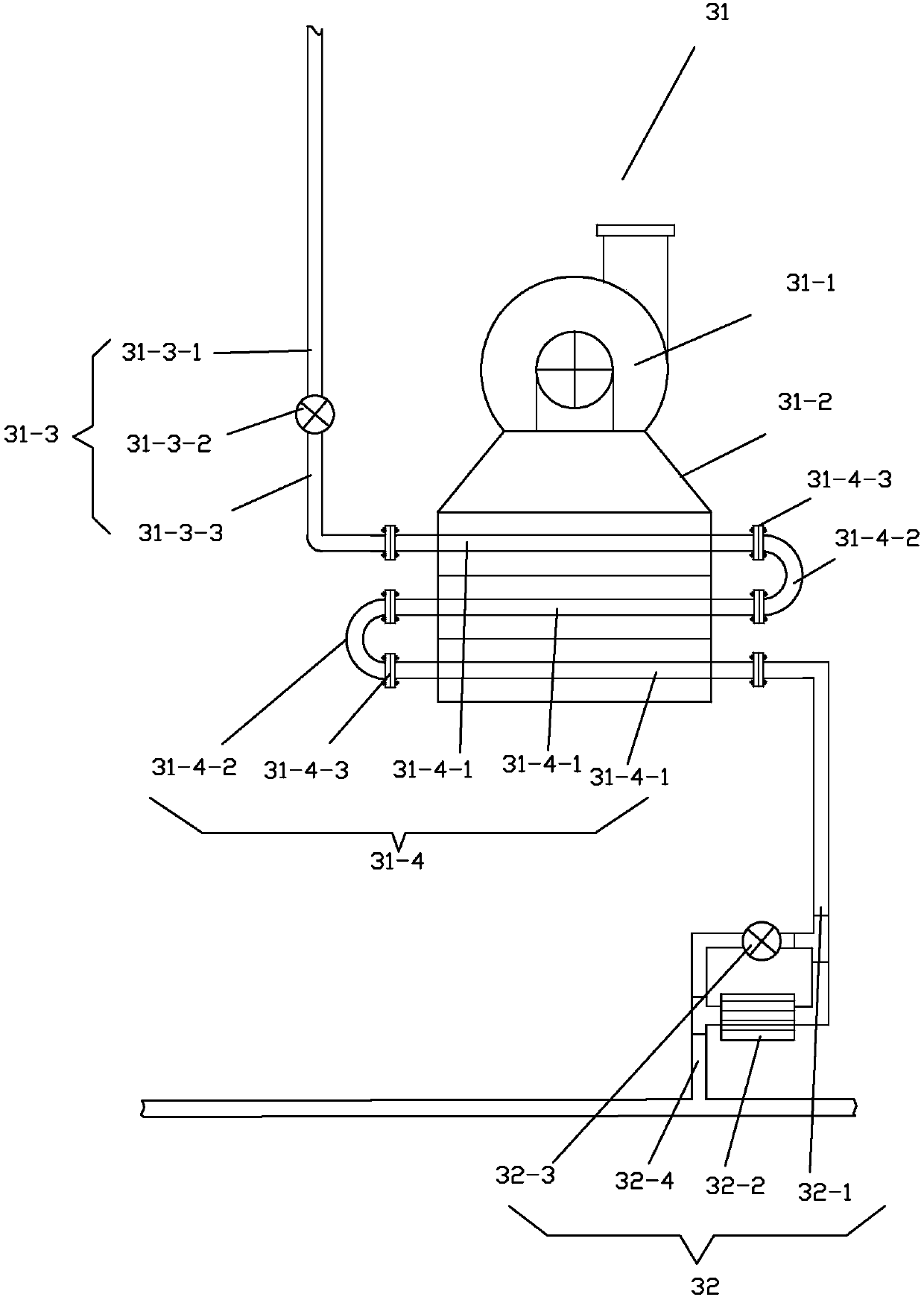
[0043] See figure 1 , the flat plate dryer suitable for drying particles after wet granulation of urea-formaldehyde molding compound in this embodiment includes a feeder 1, a box body 2, a circulating hot air drying device 3, a material conveying device 4, a cooling discharge unit 5 and a control system .

[0044] The control system includes control devices, sensors, related electric valves and related electric switches. The sensors include a plurality of temperature sensors for monitoring the temperature of the material on the conveyor belt 41 . The control device is a programmable logic controller PLC, which is used to receive the signals sent by the sensors, and send out control signals to control the opening and closing of the relevant electric valves and the on-off of the relevant electric switches after making a judgment.

[0045] Casing 2 comprises the main casing with heat preservation function and insulation partition 23, and main casing has drying casing 21 and coo...


PUM


Abstract

The invention relates to a flat plate dryer suitable for particle drying conducted after wet granulation of a urea formaldehyde molding material and a particle drying method. The flat plate dryer comprises a feeder, a box body, a hot air drying device, a material conveying device and a cooling and discharging unit. A single-stage belt type conveying device is adopted by the material conveying device. In addition, steam heaters of the selected circulating hot air drying device are arranged in the mode that hot air outlets are located above the material conveying device, the air which passes through the steam heaters can directly blow materials which are located on a conveying belt, and therefore the hot air which is outputted from the steam heaters can efficiently and directly transfer theheat to the materials, and the heat transfer efficiency is high. Compared with a multi-layer drying facility in the prior art, the flat plate dryer has the advantages of being simple in structure, lowin energy consumption, high in drying efficiency, high in productivity, safe and environmentally friendly.

Description

technical field [0001] The invention relates to the technical field of drying plastic particles, in particular to a flat plate dryer and a particle drying method suitable for drying particles after wet granulation of urea-formaldehyde molding materials. Background technique [0002] Urea-formaldehyde molding compound refers to the powdery material for compression molding that is processed into urea-formaldehyde resin by polycondensation reaction using urea and formaldehyde as raw materials, plus fillers, colorants, lubricants, plasticizers, etc. (commonly known as electric jade powder) ) or granular materials. The urea-formaldehyde molding compound is heated and molded to obtain the corresponding urea-formaldehyde plastic products. There are two traditional manufacturing methods of urea-formaldehyde molding compound. The first is a one-step process, and the second is a two-step process. [0003] The one-step process includes pulping, vacuum mixing, crushing and sieving (o...

Claims


Application Information

Patent Timeline
Patent Type & Authority Applications(China)
IPC IPC(8): F26B15/18F26B21/00F26B21/02F26B25/22
Inventor 陈瑞福秦光熙陆平陈何
Owner 溧阳市乔森塑料有限公司
Why Eureka
Try Eureka