Energy collection system and self-energy-supply wearable device
A technology of energy collection and energy, which is applied in current collectors, transportation and packaging, electric vehicles, etc., can solve the problems of unstable output voltage and current, high requirements for working environment, high voltage, etc., to ensure stability, simple manufacturing process, Effect of reducing internal resistance
- Summary
- Abstract
- Description
- Claims
- Application Information
AI Technical Summary
Problems solved by technology
Method used
Image
Examples
no. 1 example
[0041] In a first exemplary embodiment of the present disclosure, an energy harvesting system is provided.
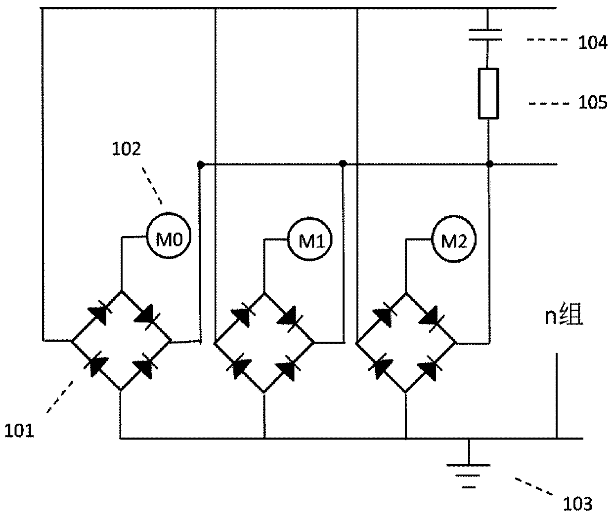
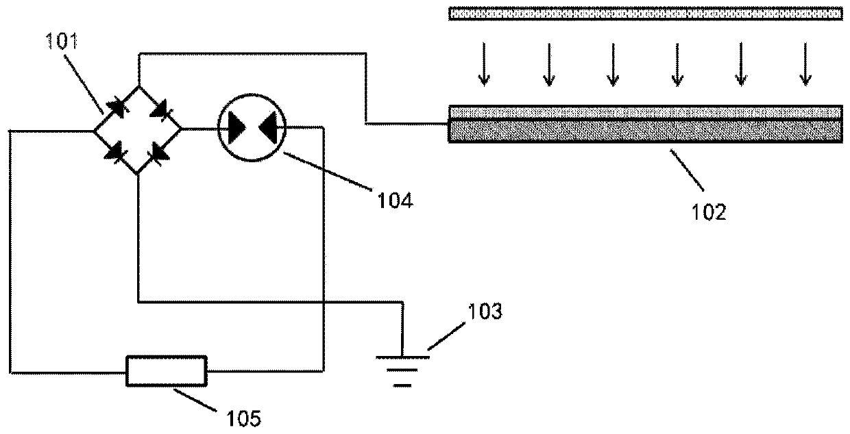
[0042] figure 1 It is a schematic structural diagram of an energy harvesting system according to an embodiment of the present disclosure. figure 2 It is a schematic structural diagram of an energy harvesting system applied to an electret generator set according to an embodiment of the present disclosure.
[0043] In this example, refer to figure 1 As shown, the energy harvesting system includes: n independent unit structures, n is a positive integer, each independent unit structure includes: a power generation system and a rectification system, wherein the power generation system includes a micro generator 102, which is used to move the human body The generated mechanical energy is converted into electrical energy; the rectification system includes a rectification circuit 101, the AC input end of the rectification circuit is connected to the output end of the micro-g...
no. 2 example
[0059] In a second exemplary embodiment of the present disclosure, an energy harvesting system is provided.
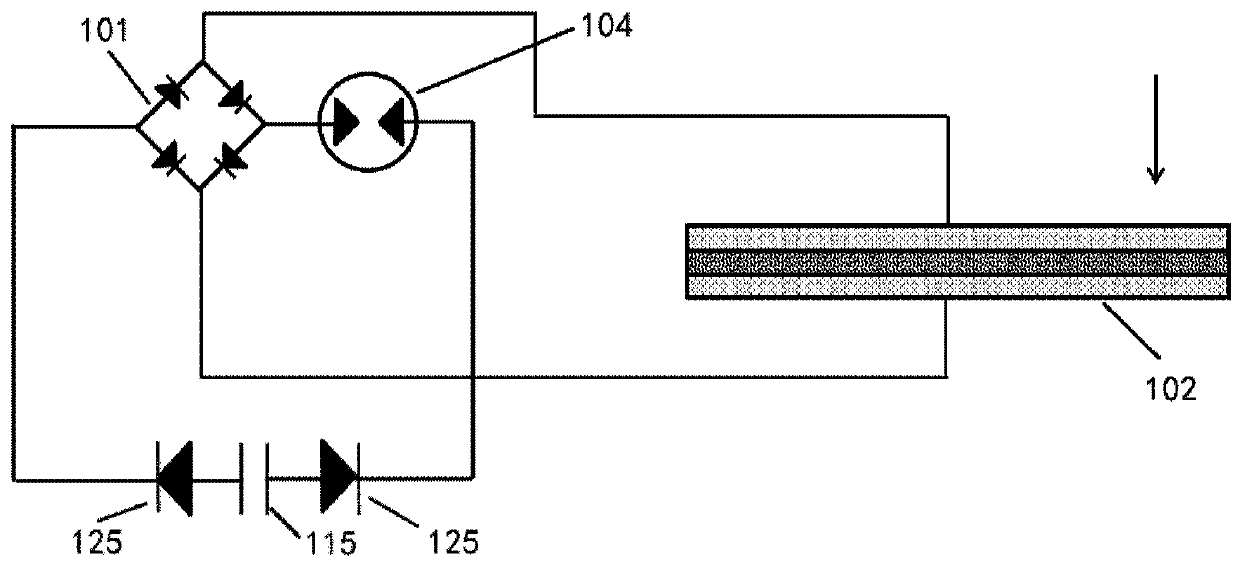
[0060] image 3 It is a schematic structural diagram of an energy harvesting system applied to a piezoelectric generator according to an embodiment of the present disclosure.
[0061] refer to image 3 As shown, the difference between this embodiment and the energy harvesting system of the first embodiment is that the micro generator in this embodiment is a piezoelectric generator, the energy harvesting system does not contain an electron source, and the piezoelectric The two output terminals of the generator are respectively connected with the two AC input terminals of the rectification circuit. In addition, an illustration of the specific form of the load is also given. In this example, refer to image 3 As shown, the load 105 is an energy storage element, such as a capacitor 115, and a diode 125 is connected in series across the capacitor to prevent current leak...
no. 3 example
[0063] In a third exemplary embodiment of the present disclosure, an energy harvesting system is provided, and the energy harvesting system is an electret power generation lighting system based on RC oscillation.
[0064] Figure 4 It is a schematic structural diagram of an electret power generation lighting system based on RC oscillation according to an embodiment of the present disclosure.
[0065] refer to Figure 4 As shown, compared with the energy harvesting system of the first embodiment, the load in this embodiment has been specifically set. In this embodiment, the load is an adjustable resistor 135 and an LED array 145, which can be The adjustable resistor 135 and the LED array 145 including n LED indicator lights are connected in series in the circuit, n≥2, by adjusting the resistance value of the adjustable resistor 135, the LED array 145 can enter a continuous flashing state, and the flashing frequency is greater than 25Hz, Can be used for steady lighting needs. ...
PUM
| Property | Measurement | Unit |
|---|---|---|
| Gap | aaaaa | aaaaa |
Abstract
Description
Claims
Application Information
 - R&D
- Intellectual Property
- Life Sciences
- Materials
- Tech Scout
- Unparalleled Data Quality
- Higher Quality Content
- 60% Fewer Hallucinations
Browse by: Latest US Patents, China's latest patents, Technical Efficacy Thesaurus, Application Domain, Technology Topic, Popular Technical Reports.
© 2025 PatSnap. All rights reserved.Legal|Privacy policy|Modern Slavery Act Transparency Statement|Sitemap|About US| Contact US: help@patsnap.com


