
Device and method for simultaneously carrying out optical detection on front surface and back surface of object

An optical detection and object technology, which is used in measurement devices, material analysis by optical means, scientific instruments, etc., can solve the problems of poor reliability, increased installation complexity, and large installation space of the mechanism, so as to reduce detection costs and be easy to install. Effects with debugging, simple structure

Pending Publication Date: 2019-05-17
QUANZHOU NORMAL UNIV
View PDF0 Cites 15 Cited by
  • Summary
  • Abstract
  • Description
  • Claims
  • Application Information

AI Technical Summary

Problems solved by technology

[0004] If you want to detect two sides of a single object at the same time, the current common detection method is that one camera occupies one station to detect one surface. If you need to detect the front and back sides or even multiple sides, you need to use multiple cameras to occupy multiple stations. In this way As a result, the installation space of the mechanism is very large, and multiple sets of mechanism installation modules and multiple sets of circuit modules are required at the same time, which increases the complexity of installation and leads to poor reliability.

Method used


Image

  • Device and method for simultaneously carrying out optical detection on front surface and back surface of object
  • Device and method for simultaneously carrying out optical detection on front surface and back surface of object
  • Device and method for simultaneously carrying out optical detection on front surface and back surface of object

Examples


Embodiment Construction

[0031] In order to make the features and advantages of this patent more obvious and easy to understand, 2 examples are given below, which are described in detail as follows:

[0032] Such as figure 1 As shown, in the field of machine vision, a set of traditional optical detection devices in the prior art mainly includes a camera 100, a lens 200, and a coaxial light source 300, and a set of devices can only detect one surface of the object 400 to be tested.

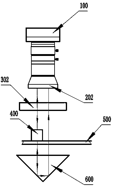
[0033] Such as figure 2 As shown, in the first embodiment of the present invention, the overall device includes: a transparent object stage 500, a rectangular prism 600 arranged on one side of the transparent object stage 500, and a rectangular prism 600 arranged on the other side of the transparent object stage 500 Coaxial illumination telecentric imaging lens 201 and camera 100; the slope of rectangular prism 600 faces the transparent stage 500 and is parallel to transparent stage 500; rectangular prism 600, coaxial il...


PUM


Abstract

The invention provides a device and a method for simultaneously carrying out optical detection on the front surface and the back surface of an object. The device is characterized by comprising a transparent object stage, a right-angle prism arranged on one side of the transparent object stage, a light source, a telecentric imaging lens and a camera, wherein the light source, the telecentric imaging lens and the camera are arranged on the other side of the transparent object stage; the inclined plane of the right-angle prism faces the transparent object stage and is parallel to the transparentobject stage; the right-angle prism, the telecentric imaging lens and the camera are coaxial. The method mainly adopts the secondary reflection of the right-angle prism to realize the simultaneous detection of the front surface and the back surface of the same object to be detected, and simultaneously adopts the machine vision telecentric optical imaging lens to obtain a depth of field that is large enough, so that the front surface and the back surface of the object to be detected can be clearly imaged. According to the scheme, the two surfaces of the object to be detected can be detected byone light source and one camera, the detection cost is greatly reduced on the premise of guaranteed efficiency, and the device is simple in structure, easy to install and debug and high in practical and popularization values.

Description

technical field [0001] The invention belongs to the fields of optical detection and machine vision, and in particular relates to a device and method for optically detecting the front and back surfaces of an object simultaneously. Background technique [0002] Machine vision is a device that uses machines instead of human eyes to measure and judge. Traditional machine vision optical automatic inspection devices use a camera and a light source to detect a surface of the object to be inspected. If multiple surfaces need to be inspected, machine vision optical inspection equipment with multiple sets of cameras is required. There are disadvantages of cost and reliability in accomplishing the detection task in this way. [0003] Such as figure 1 As shown, in the field of machine vision, a set of traditional optical detection devices mainly includes cameras, lenses, coaxial light sources, image processing software, objects to be measured, etc. That is, the object is illuminated...

Claims


Application Information

Patent Timeline
Patent Type & Authority Applications(China)
IPC IPC(8): G01N21/84G01N21/01
Inventor 廖廷俤郭志伟苏龙龙吴平辉
Owner QUANZHOU NORMAL UNIV
Learn More